
A handy way to remember these relationships is the distance, speed, time triangle:
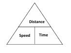
Here's how to use it:
This triangle visually simplifies the formulas and makes them easier to recall.
The fundamental formula we'll use is:
Remember to ensure that the units of speed and time are compatible. For example:
If the units are different, you'll need to convert them before applying the formula.
              Velocity (m/s)
              |
            20|------------------------
              |                       |
              |                       |
              |                       |
              |_______________________|
              0       10      Time (s)
              Velocity (m/s)
              |
            30|----------------------/
              |                     /
              |                    /
              |                   /
              |__________________/
              0       10      Time (s)
              Distance (m)
              |
            50|---------------------/
              |                    /
              |                   /
              |                  /
              |_________________/
              0       10      Time (s)
              Distance (m)
              |
              |         .-'
              |      .-'
              |   .-'
              |.-'
              |________________________
              0          Time (s)
An object at rest stays at rest, and an object in motion stays in motion with a constant velocity, unless acted upon by a net external force. 1
The acceleration of an object is directly proportional to the net force acting on it and inversely 2 proportional to its mass.
Mathematically: F = ma (where F is force, m is mass, and a is acceleration). 3
For every action, there is an equal and opposite reaction. When one object exerts a force on a second object, 4 the second object simultaneously exerts a force equal in magnitude and opposite in direction on the first object. 5
Question: A box with a mass of 5 kg is pushed with a force of 20 N. Calculate the acceleration of the box.
Working:
Answer: The acceleration of the box is 4 m/s².
Question: A car with a mass of 1200 kg accelerates from rest to a speed of 30 m/s in 10 seconds. Calculate the force required for this acceleration.
Working:
Answer: The force required is 3600 N.
Question: A bowling ball with a mass of 7 kg is moving at 10 m/s. It must be stopped within 2 seconds. What force is required to decelerate the ball?
Working:
Answer: The force required is 35 N. The negative sign indicates that the force is acting in the opposite direction of the ball's motion.
| Feature | Uniform Velocity | Variable Velocity |
|---|---|---|
| Definition | Velocity remains constant in both magnitude and direction. | Velocity changes in magnitude, direction, or both. |
| Acceleration | Zero acceleration. | Non-zero acceleration. |
| Distance-Time Graph | Straight, sloping line. | Curved line or a series of straight lines with different slopes. |
| Velocity-Time Graph | Horizontal line. | Sloping or curved line. |
| Motion | Movement in a straight line at a constant speed. | Movement with changing speed or direction, or both. |
| Example | A car traveling on a straight highway at a constant 60 km/h. | A car accelerating from a stop, or a car going around a curve. |
| Mathematical Representation | v = constant | v = a function of time. v(t) |
Definition: A force is a push or pull upon an object resulting from the object's interaction with another object. It is a vector quantity, 1 meaning it has both magnitude and direction.
Characteristics:
| Feature | Resultant | Equilibrant |
|---|---|---|
| Definition | The single force that produces the same effect as all the individual forces acting together. | The force that, when added to the resultant, produces equilibrium (net force of zero). |
| Purpose | To find the combined effect of multiple forces. | To balance or cancel out the resultant force. |
| Direction | The direction of the net force. | Opposite in direction to the resultant force. |
| Magnitude | The magnitude of the net force. | Equal in magnitude to the resultant force. |
| Effect | Causes acceleration. | Causes no acceleration, maintains equilibrium. |
| Mathematical operation | found by vector addition of all forces. | Found by calculating the negative of the resultant force. |
When forces act along a straight line (collinear forces), they can be:
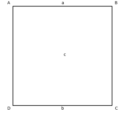
The parallelogram of forces is a method used in physics and engineering to determine the resultant of two forces acting at a point. It states that: If two forces acting simultaneously on a body at a point are represented in magnitude and direction by the two adjacent sides of a parallelogram, then the diagonal of the parallelogram represents their resultant in both magnitude and direction.
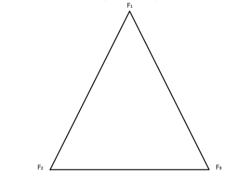
The triangle of forces is a method used to analyze equilibrium conditions. It states that: If three forces acting at a point are in equilibrium, they can be represented in magnitude and direction by the sides of a triangle taken in order.
Bow's Notation is a system of labelling used in structural mechanics and force diagrams.
To solve triangle of forces problems graphically, follow these steps:
Given:
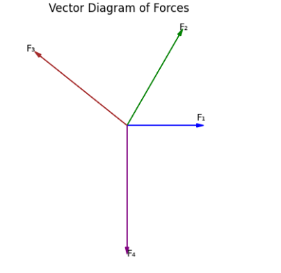
The polygon of forces is a graphical method used to find the resultant of more than two forces acting at a point.
If several forces acting at a point are represented in magnitude and direction by the sides of a closed polygon taken in order, then the system of forces is in equilibrium. If the polygon does not close, the closing side represents the resultant force.
Given Forces:
Imagine a force acting at an angle. We can think of this force as having two separate effects: one acting horizontally and one acting vertically. These are the horizontal and vertical components of the force.
Let's say a force of 100 N acts at an angle of 30 degrees to the horizontal.
Where:
There are three classes of levers, categorized by the relative positions of the fulcrum (pivot point), the effort (force applied), and the load (resistance):
It is important to note that when the force is perpendicular to the radius, sin(90)=1, and the equation simplifies to Torque = Force x Radius, which is the same as moment of force.
Energy is the capacity to do work.
Energy of motion.
Stored energy.
Energy stored due to height.
Energy stored in a stretched or compressed object.
Heat energy.
Energy stored in chemical bonds.
Energy of moving electrons.
Energy stored in the nucleus of an atom.
Energy of electromagnetic waves (light, etc.).
A 3 kg object is placed on a shelf 4 meters above the ground. Calculate its gravitational potential energy.
The potential energy is 117.6 Joules.
We use the formula for gravitational potential energy.
A car with a mass of 1000 kg is moving at a speed of 20 m/s. Calculate its kinetic energy.
The kinetic energy is 200,000 Joules.
We use the formula for kinetic energy.
A 1 kg ball is dropped from a height of 10 meters. Calculate its kinetic energy just before it hits the ground.
The kinetic energy just before hitting the ground is 98 Joules.
We apply the principle of conservation of energy. The initial potential energy is converted into kinetic energy.
Tractive effort is the force exerted by a vehicle's engine or motor to propel it forward. It's the force that overcomes resistance and accelerates the vehicle.
Resistance is the opposing force that hinders the motion of a vehicle. It includes factors like rolling resistance, air resistance, and gradient resistance.
A car traveling at a constant speed on a level road experiences a resistance of 500 N. What is the tractive effort?
The tractive effort is 500 N.
Because the car is moving at a constant speed, the tractive effort and resistance are equal.
A train with a mass of 10,000 kg accelerates at 0.5 m/s2 on a level track. The resistance is 2,000 N. What is the tractive effort?
The tractive effort is 7,000 N.
We use Newton's second law to calculate the force required for acceleration, then add the resistance.
A truck with a mass of 5000kg is traveling at a constant velocity on a flat road. The rolling resistance is equal to 0.02 times the weight of the truck. calculate the tractive effort.
The tractive effort is 980N.
In this case, the only resistance is rolling resistance, so the tractive effort is equal to it.
A car with a weight of 15,000 N travels up a 10-degree incline at a constant speed. The resistance is 800 N. What is the tractive effort?
The tractive effort is 3,404 N.
We add the resistance and the component of weight acting down the incline.
A truck with a mass of 8,000 kg accelerates at 0.2 m/s2 up a 5-degree incline. The resistance is 1,200 N. What is the tractive effort?
The tractive effort is 9,636 N.
We consider the force for acceleration, resistance, and the component of weight acting down the incline.
A bicycle and rider with a combined weight of 800N are traveling down a 7 degree incline at a constant velocity. The air resistance is 50N. what is the required braking force?
The required braking force is 47.44N.
In this case, the component of weight acting down the incline must be countered by the air resistance and the braking force.
Work done in rotation occurs when a torque causes an object to rotate about an axis. It's the energy transferred due to a rotational force acting over an angular displacement.
Mathematically, work done in rotation (W) is given by: W = τ × θ, where τ is the torque and θ is the angular displacement (in radians).
The engine of a motor vehicle produces torque, which is the rotational force that turns the crankshaft.
This torque is then transmitted through the drivetrain (clutch, gearbox, differential) to the wheels.
The torque applied to the wheels causes them to rotate.
The work done in rotating the wheels propels the vehicle forward.
Gear ratios in the transmission affect the torque and angular velocity of the wheels.
Lower gears provide higher torque for acceleration, while higher gears provide lower torque for cruising at higher speeds.
The work done in rotation is directly related to the power output of the engine.
Power is the rate at which work is done (Power = Torque × Angular Velocity).
The work done in rotation is therefore vital to a motor vehicles ability to accelerate, and to overcome resistances.
For work done in linear motion, a force-distance graph represents the force applied against the distance moved.
The area under the force-distance curve represents the work done.
If the force is constant, the graph is a horizontal line, and the area is a rectangle (Work = Force × Distance).
If the force varies, the area can be calculated using integration or by approximating it with geometric shapes.
While a force-distance graph is typically used for linear motion, you can adapt the concept to rotational motion.
Instead of force, you would use torque (τ).
Instead of distance, you would use angular displacement (θ).
A torque-angular displacement graph would then represent the work done in rotation.
The area under the torque-angular displacement curve would represent the work done in rotation (Work = Torque × Angular Displacement).
Because torque is a rotational force, and angular displacement is a rotational distance, the area under the torque vs angular displacement graph is still work done.
Imagine a graph with torque (τ) on the vertical axis and angular displacement (θ) on the horizontal axis.
If the torque is constant, the graph is a horizontal line.
The area under this line is a rectangle, and its area represents the work done (W = τ × θ).
If the torque varies, the graph is a curve, and the area under the curve represents the work done.
Power is the rate at which work is done or energy is transferred.
In simpler terms, it tells us how quickly work is being done.
The SI unit for power is the Watt (W).
1 Watt is equal to 1 Joule per second (1 W = 1 J/s).
Horsepower (hp) is a unit of power commonly used in the automotive industry and other applications.
The relationship between Watts and horsepower is:
The formula for power is:
Power (P) = Work (W) / Time (t)
Or, since Work = Force x Distance, Power (P) = (Force x Distance) / time.
A machine does 1500 Joules of work in 5 seconds. Calculate the power output of the machine.
The power output of the machine is 300 Watts.
We simply divided the work done by the time taken.
A motor lifts a 50 kg object to a height of 10 meters in 20 seconds. Calculate the power output of the motor.
The power output of the motor is 245 Watts.
We first calculated the work done in lifting the object, then divided that work by the elapsed time.
A car engine exerts a force of 2000 N to move the car a distance of 500 meters in 25 seconds. What is the power output of the engine?
The power output of the engine is 40,000 Watts or 40 Kilowatts.
We calculated the work done by the engine, then divided that work by the time taken to find the power.
The intake valve opens, and the piston moves downward, drawing in a mixture of air and fuel (in a gasoline engine) or just air (in a diesel engine).
Both intake and exhaust valves are closed.
The piston moves upward, compressing the air-fuel mixture (or air alone), increasing its temperature and pressure.
Near the top of the compression stroke, the air-fuel mixture is ignited by a spark plug (gasoline) or by the high temperature of the compressed air (diesel).
The rapid combustion creates a large amount of heat and pressure.
The expanding gases force the piston downward, producing power.
The exhaust valve opens, and the piston moves upward, expelling the burned gases from the cylinder.
This cycle repeats.
Indicated power is the theoretical power developed inside the engine cylinders by the combustion of fuel. It represents the power available before any losses due to friction or other factors.
Formula (for one cylinder):
IP = (PLAN) / 60
Brake power is the actual power delivered by the engine at the crankshaft or flywheel. It is the power available to drive the vehicle or machinery after accounting for friction and other losses.
Formula:
BP = (2πNT) / 60
For an engine with multiple cylinders, multiply the indicated power of one cylinder by the number of cylinders.
IP (engine) = IP (one cylinder) × Number of cylinders.
A four-stroke engine cylinder has an IMEP of 800 kPa, a stroke length of 100 mm, a bore of 80 mm, and operates at 3000 RPM. Calculate the indicated power.
The indicated power of one cylinder is approximately 1.67 kW.
A four-cylinder engine has the same specifications as in Example 1. Calculate the total indicated power.
The total indicated power of the engine is approximately 6.68 kW.
We multiplied the power of a single cylinder by the total number of cylinders.
As mentioned before, brake power (BP) is the power delivered at the engine's crankshaft or flywheel.
The formula used is:
BP = (2πNT) / 60
To determine brake power, you need to measure the torque produced by the engine at a specific RPM. This is typically done using a dynamometer.
The Farnborough indicator is a device used to measure the pressure inside an engine cylinder during the combustion cycle.
It produces a pressure-volume (PV) diagram, which shows the changes in cylinder pressure as the piston moves.
From the PV diagram:
The Farnborough indicator provides a graphical record of the cylinder pressure, allowing engineers to analyze the combustion process and identify any irregularities.
The Morse test is a method used to determine the indicated power (IP) of a multi-cylinder internal combustion engine.
From the Morse test, the IP of each cylinder is calculated as the difference between the BP with all cylinders firing and the BP with that cylinder cut out.
Then the total IP of the engine is the sum of all the individual cylinder IP values.
Friction power is the power lost due to friction within the engine.
Let's say a four-cylinder engine has the following brake power readings:
This result shows that the initial BP measurement was flawed, as the IP should be higher than the BP. In real world situations, this would mean the test should be re-run. If we assume the BP was 30kW, instead of 40kW, then the FP would equal 4kW.
The Morse test allows you to determine the contribution of each cylinder to the total indicated power.
By comparing the IP and BP, you can quantify the power lost due to friction.
Mechanical efficiency (ηm) is the ratio of brake power (BP) to indicated power (IP). It represents the proportion of the indicated power that is actually delivered at the crankshaft or flywheel, accounting for friction losses.
𝜂m = (BP / IP) × 100%
Therefore the higher the mechanical efficiency, the less power is lost to friction.
An engine has an indicated power of 50 kW and a brake power of 40 kW. Calculate its mechanical efficiency.
The mechanical efficiency of the engine is 80%.
Fuel consumption is the amount of fuel an engine uses per unit of time or distance. It is a key indicator of engine efficiency and operating cost.
Fuel consumption is typically measured in liters per 100 kilometers (L/100 km) or miles per gallon (mpg).
Specific fuel consumption (SFC) is the amount of fuel consumed per unit of power output per unit of time (e.g., kg/kWh). This is a measurement of how efficiently an engine turns fuel into power.
Thermal efficiency (𝜂th) is the ratio of the work done by the engine to the heat energy supplied by the fuel. It represents how effectively the engine converts the chemical energy of the fuel into mechanical work.
𝜂th = (Work Output / Heat Input) × 100%
Thermal efficiency is always less than 100% due to heat losses and other inefficiencies.
Friction is a force that opposes the relative motion or tendency of relative motion of two surfaces in contact.1 It acts parallel to the surfaces and in the opposite direction of motion or intended motion.2
o Description: Boundary friction occurs when two surfaces are in contact with each other, but there is a very thin layer of lubricant or contaminants between them.3 The lubricant layer is not thick enough to completely separate the surfaces, so some direct contact occurs.4
o Characteristics:
o Examples in Motor Vehicles:
o Description: Dry friction occurs when two solid surfaces are in direct contact with each other, with no lubricant present.8
o Characteristics:
o Examples in Motor Vehicles:
o Description: Fluid friction occurs when there is a fluid (liquid or gas) between the surfaces.13 The fluid acts as a lubricant, separating the surfaces and reducing friction.14
o Characteristics:
o Examples in Motor Vehicles:
The type of materials in contact significantly affects friction. Rougher surfaces generally have higher friction than smoother surfaces.
The force pressing the surfaces together (normal force) directly influences frictional resistance. A greater normal force results in higher friction.
The degree of roughness or smoothness of the surfaces. Rougher surfaces interlock more, increasing friction.
Lubricants reduce friction by separating the surfaces, creating a fluid film.
Temperature can affect the properties of materials and lubricants, influencing friction.
In some cases, the relative velocity between the surfaces can affect friction, especially in fluid friction.
The force of friction is directly proportional to the normal force pressing the surfaces together.
The force of friction is independent of the apparent area of contact between the surfaces.
The force of friction depends on the nature of the materials in contact.
The force of static friction (opposing the start of motion) is generally greater than the force of kinetic friction (opposing motion once it has started).
Formula:
Frictional Force (Ff) = Coefficient of Friction (μ) × Normal Force (N)
Ff = μN
o Where:
Question: A 50 kg box rests on a horizontal floor. The coefficient of static friction between the box and the floor is 0.4. Calculate the force required to start moving the box.
Working:
N = mg = 50 kg × 9.8 m/s2 = 490 N
Ff = μsN = 0.4 × 490 N = 196 N
Answer: The force required to start moving the box is 196 N.
Explanation: We calculated the normal force (weight) and then applied the friction formula.
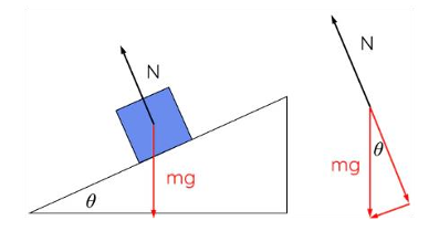
Question: A 100 N block is placed on an inclined plane at an angle of 30 degrees. The coefficient of kinetic friction is 0.2. Calculate the frictional force acting on the block as it slides down the plane.
Working:
N = Wcos(θ) = 100 N × cos(30°) ≈ 86.6 N
Ff = μkN = 0.2 × 86.6 N ≈ 17.32 N
Answer: The frictional force is approximately 17.32 N.
Explanation: We calculated the normal force component and then applied the friction formula.
Question: A 20 kg object is pulled horizontally with a force of 80 N, and it moves at a constant velocity. Calculate the coefficient of kinetic friction.
Working:
N = mg = 20 kg × 9.8 m/s2 = 196 N
Ff = 80 N (since the object moves at a constant velocity, the applied force equals the frictional force)
μk = Ff / N = 80 N / 196 N ≈ 0.408
Answer: The coefficient of kinetic friction is approximately 0.408.
Explanation: We used the given forces and the normal force to calculate the coefficient of friction.
Question: A 10kg box is resting on an incline of 20 degrees. The coefficient of static friction is 0.3. What force parallel to the incline is required to prevent the box from sliding down?
Working:
N = mg×cos(θ) = 10kg ×9.8ms2×cos(20) = 98N × 0.9396 = 92.08N
Ff = μs×N = 0.3 × 92.08N = 27.62N
Force due to gravity down the incline = mg × sin(θ) = 10kg × 9.8ms2 ×sin(20) = 98N × 0.342 = 33.52N.
Force required = Force due to gravity − Frictional force.
Force required = 33.52N − 27.62N = 5.9N.
Answer: The force required is 5.9N.
Explanation: We calculate the components of the weight force, and the maximum static frictional force, and then subtract the frictional force from the force due to gravity.
o These bearings consist of a cylindrical bush (a sleeve) that fits into a housing, with a rotating shaft inside.
o Friction:
o These bearings consist of two or more half-shells that fit around a journal (shaft).
o Friction:
Frictional Torque (Tf) = Frictional Force (Ff) × Radius (r)
Ff = μN (where μ is the coefficient of friction and N is the normal force)
Therefore Tf = μNr.
o Question: A shaft rotating in a bushed bearing has a load of 5000 N. The bearing radius is 50 mm, and the coefficient of friction is 0.02. Calculate the frictional torque.
o Working:
o Answer: The frictional torque is 5 Nm.
o Explanation: We applied the frictional torque formula, using the given load, radius, and coefficient of friction.
o A clutch is a mechanical device that engages or disengages power transmission between two rotating shafts, typically an engine and a transmission.
o It relies on friction to transmit torque.
o When the clutch is engaged, friction between the clutch plate and the flywheel (or pressure plate) transmits torque from the engine to the transmission.
o When the clutch is disengaged, the clutch plate is separated from the flywheel, interrupting torque transmission.
o The amount of torque transmitted depends on the frictional force between the clutch surfaces and the radius of the clutch plate.
o Factors affecting torque transmission:
o When the clutch pedal is depressed, a mechanism overcomes the spring pressure, and separates the clutch plate from the flywheel.
o The clutch allows for smooth engagement and disengagement of power, enabling gear changes and preventing engine stalling.
o The material of the clutch facing determines the coefficient of friction. Higher friction materials transmit more torque.
o Multi-plate clutches have multiple friction surfaces, increasing the torque capacity. More friction surfaces results in greater torque transmission.
o A larger mean radius provides a greater moment arm, allowing for more torque to be transmitted.
o The force pressing the clutch plates together is critical. Greater axial force increases the frictional force and thus the torque capacity.
o Worn, glazed, or contaminated clutch surfaces reduce the coefficient of friction, decreasing torque transmission.1
T = μ × Fa × rm × n
o Where:
o Question: A single-plate clutch has a mean radius of 0.15 meters, an axial force of 3000 N, and a coefficient of friction of 0.3. Calculate the torque transmitted.
o Working:
T = μ × Fa × rm × n
T = 0.3 × 3000 N × 0.15 m × 2 (There are 2 friction surfaces on a single plate clutch)
T = 270 Nm
o Answer: The torque transmitted is 270 Nm.
o Explanation: We applied the torque formula, using the given values.
The clutch safety factor is the ratio of the maximum torque the clutch can transmit to the engine torque. It ensures the clutch can handle the engine's power output without slipping.
Safety Factor = Maximum Clutch Torque / Engine Torque
o A safety factor greater than 1 indicates that the clutch can transmit more torque than the engine produces.
o A higher safety factor provides a margin of safety, accounting for variations in operating conditions, wear, and other factors.
o For example a safety factor of 1.5 would mean the clutch can handle 1.5 times the engines torque output.3
o Prevents clutch slippage, which can lead to overheating and premature wear.4
o Ensures reliable power transmission under various loads and conditions.
o Higher pressure applied to the clutch friction material increases the normal force between the clutch plate and the flywheel or pressure plate.
o As frictional force is directly proportional to normal force, this results in a greater torque transmission capacity.
o Increased pressure leads to higher frictional forces, which in turn generate more heat.
o Excessive heat can cause:
o Higher pressure can accelerate the wear rate of the clutch friction material, especially if combined with high temperatures or slippage.
o Clutch design aims to achieve an optimal pressure that balances torque transmission capacity with acceptable wear and heat generation.
o Too little pressure leads to slippage, while too much pressure leads to excessive wear and heat.
o Lubricants create a thin film between surfaces, reducing direct contact and thus minimizing friction.3
o This reduces wear, heat generation, and power loss.4
o Lubricants prevent direct contact between surfaces, reducing abrasive wear and extending the lifespan of components.5
o Lubricants can carry away heat generated by friction, preventing overheating and thermal damage.6
o Lubricants can form a protective barrier against moisture and corrosive substances, preventing rust and corrosion.7
o Lubricants can dampen vibrations and reduce noise generated by friction.8
o Boundary Lubrication: Occurs when the lubricant film is very thin, and some direct contact occurs.9
o Fluid Lubrication (Hydrodynamic/Hydrostatic): Occurs when a full fluid film separates the surfaces, minimizing friction.10
o Under heavy loads and high pressures, conventional lubricants may fail to provide adequate protection.
o EP additives are chemical compounds that form a protective layer on metal surfaces, preventing welding and scuffing under extreme pressure conditions.11
o Hypoid gears, commonly used in vehicle differentials, have sliding contact between the gear teeth, resulting in very high pressures and temperatures.12
o Hypoid oils are specifically formulated with EP additives to withstand these extreme conditions.13
o Heavy loads increase the pressure between gear teeth and other contacting surfaces.
o EP or hypoid oils are essential to prevent wear and damage in these applications.
o High Load-Carrying Capacity: Must withstand high pressures without breaking down.
o Anti-Wear Properties: Must protect against wear and scuffing.
o Thermal Stability: Must maintain its properties at high temperatures.
o Oxidation Resistance: Must resist degradation due to oxidation.
o Corrosion Protection: Must protect against rust and corrosion.
o Vehicle differentials with hypoid gears.
o Heavy-duty transmissions and gearboxes.
o Industrial gear drives operating under high loads.
When a force is applied to a material, it can cause:
o Deformation: A change in the shape or size of the material.1
o Stress: Internal resistance to the applied force.
o Strain: The measure of deformation.2
o Fracture: Breaking or failure of the material.3
o The degree of these effects depends on the magnitude and type of force, as well as the material's properties.
Definition: Stress (σ) is the force (F) acting per unit area (A).
Formula: σ = F / A4
Example:
o Question: A steel rod with a cross-sectional area of 0.001 m2 is subjected to a tensile force of 10,000 N. Calculate the stress.
o Working:
σ = F / A5
σ = 10,000 N / 0.001 m2
σ = 10,000,000 Pa or 10 MPa
o Answer: The stress is 10 MPa.
o Explanation: We divided the applied force by the cross-sectional area.
Definition: Strain (ε) is the change in length (ΔL) divided by the original length (L).6
Formula: ε = ΔL / L7
Example:
o Question: A 2-meter-long metal bar is stretched by 2 mm. Calculate the strain.
o Working:
ΔL = 2 mm = 0.002 m
L = 2 m
ε = ΔL / L8
ε = 0.002 m / 2 m
ε = 0.001 (dimensionless)
o Answer: The strain is 0.001.
o Explanation: We divided the change in length by the original length.
Definition: Elasticity is the ability of a material to return to its original shape after the removal of an applied force.9
Hooke's Law: Within the elastic limit, stress is directly proportional to strain.10
σ = Eε
o Where E is the modulus of elasticity (Young's modulus).
Example:
o Question: A material has a Young's modulus of 200 GPa. If a stress of 400 MPa is applied, calculate the strain.
o Working:
σ = 400 MPa = 400,000,000 Pa
E = 200 GPa = 200,000,000,000 Pa
ε = σ / E
ε = 400,000,000 Pa / 200,000,000,000 Pa
ε = 0.002
o Answer: The strain is 0.002.
o Explanation: We divided the stress by Young's modulus.
o A pulling force that tends to stretch or elongate a material.11
o Example: Tension in a tow cable, or in the bolts holding a cylinder head.
o A pushing force that tends to compress or shorten a material.
o Example: Compression in suspension springs, or in engine connecting rods during the power stroke.
o A force that tends to cause one part of a material to slide past another.12
o Example: Shear force in bolts holding a wheel hub, or in the rivets joining body panels.
o A combination of two or more of the above forces acting simultaneously.
o Example: Forces on a crankshaft during engine operation, which involve tension, compression, and shear.
o A twisting force that tends to rotate a material.13
o Example: Torsion in a drive shaft, or in the axles of a vehicle.
o Description: A pulling force that elongates a material.
o Sketch:
<----- [Material] ----->
F_tensile F_tensile
o The arrows indicate the direction of the tensile force, pulling the material apart.
o Description: A pushing force that shortens a material.
o Sketch:
-----> [Material] <-----
F_compressive F_compressive
o The arrows indicate the direction of the compressive force, pushing the material together.
o Description: A force that causes one part of a material to slide past another.
o Sketch:
[Material Top Surface] ----->
<----- [Material Bottom Surface]
F_shear
o The arrows indicate the opposing forces causing the sliding motion.
o Description: A combination of two or more of the above forces.
o Sketch: This is difficult to represent with a simple text sketch, as it varies depending on the combination. Imagine a crankshaft, where you have tension, compression, and shear all occurring at the same time.
o Description: A twisting force that rotates a material.
o Sketch:
[Material]
|
/ \ <-- Twisting motion
| |
\ / <-- Twisting motion
|
o The curved arrows indicate the twisting motion.
o Tow cables under load.
o Timing belts.
o Bolts holding cylinder heads.
o Tie rods.
o Suspension springs.
o Engine connecting rods during compression and power strokes.
o Vehicle chassis when loaded.
o Pillars of the car during a roll over.
o Bolts holding wheel hubs.
o Rivets joining body panels.
o Keyways in shafts.
o Brake caliper bolts.
o Crankshaft during engine operation.
o Suspension components during cornering.
o Gear teeth.
o Drive shafts.
o Axles.
o Crankshaft.
o Steering shafts.
Stress (normal or direct) is the internal resistance offered by a material to an externally applied force per unit area. It is the force that molecules of the material exert on each other to resist deformation.
Stress (σ) = Force (F) / Area (A)
o SI units: Pascal (Pa) or Newtons per square meter (N/m2)
1 Pa = 1 N/m2
o Common units: Megapascals (MPa), Kilopascals (kPa), Pounds per square inch (psi).
Definition: Direct strain (ε) is the measure of deformation of a material when subjected to a force.1 It is defined as the change in length (ΔL) divided by the original length (L).2
Formula: ε = ΔL / L
Explanation: Strain is a dimensionless quantity, as it is a ratio of two lengths.3 It represents the amount of deformation per unit length.4
o If the load is within the elastic limit, the material will deform but return to its original shape when the load is removed.5
o If the load exceeds the elastic limit, the material will undergo permanent deformation, meaning it will not return to its original shape.6
o At the yield point, the material begins to deform significantly with little or no increase in load.
o If the load continues to increase beyond the ultimate tensile strength, the material will eventually fracture or break.
o Repeated overloading can lead to fatigue failure, even if the load is below the yield strength.7 This occurs due to the accumulation of microscopic damage.
o Under sustained loading at elevated temperatures, materials can experience creep, which is a slow and continuous deformation over time.8
Question: A steel wire with an original length of 5 meters is stretched by 5 mm when a tensile force of 1000 N is applied. The wire has a cross-sectional area of 1 mm2. Calculate the stress and strain.
Working:
o Stress (σ) = Force (F) / Area (A)9
o Strain (ε) = Change in length (ΔL) / Original length (L)10
Answer: The stress is 1 GPa, and the strain is 0.001.
Explanation: We applied the stress and strain formulas using the given values.
Question: A concrete cylinder with a diameter of 150 mm and a height of 300 mm is subjected to a compressive force of 500 kN. Calculate the stress and strain if the height decreases by 0.5 mm.
Working:
o Area (A) = π(d/2)2 = π(0.15 m / 2)2 ≈ 0.01767 m2
o Stress (σ) = Force (F) / Area (A)11
o Strain (ε) = Change in length (ΔL) / Original length (L)12
Answer: The stress is approximately 28.3 MPa, and the strain is approximately 0.00167.
Explanation: We calculated the area, and then applied the stress and strain formulas.
Question: A steel rod with an original length of 2 meters and a cross-sectional area of 2 cm2 is subjected to a tensile force of 40 kN. If the rod elongates by 1 mm, calculate the Young's modulus of the steel.
Working:
o Stress (σ) = Force (F) / Area (A)13
o Strain (ε) = Change in length (ΔL) / Original length (L)14
o Young's Modulus (E) = Stress (σ) / Strain (ε)16
Answer: The Young's modulus of the steel is 400 GPa.
o Explanation: Calculated stress and strain, then derived Youngs Modulus.
The relationship between stress and strain is fundamental to understanding how materials behave under load.1
Hooke's Law: Within the elastic limit of a material, stress is directly proportional to strain.2 This linear relationship is expressed as:
o σ = Eε3
This means that as stress increases, strain increases proportionally, provided the material remains within its elastic range.5
Beyond the elastic limit, the relationship becomes non-linear, and the material may undergo permanent deformation.6
A load-extension diagram (or stress-strain diagram) illustrates the behaviour of a material under tensile load.7
o This is the point on the diagram up to which stress is directly proportional to strain.8
o Hooke's law is valid up to this point.9
o Beyond this point, the relationship between stress and strain becomes non-linear.
o This is the maximum stress that a material can withstand without permanent deformation.10
o If the load is removed before reaching this point, the material will return to its original shape.11
o Beyond this point, the material will undergo plastic deformation.
o This is the point at which the material begins to deform significantly without a substantial increase in load.12
o There may be an upper and lower yield point, with a slight drop in load at the upper yield point.13
o This is where plastic deformation begins.
o This is the highest load (or stress) that the material can withstand before it begins to neck down (reduce in cross-sectional area).
o Beyond this point, the load-carrying capacity of the material decreases.
o This is the point at which the material breaks or fractures.
o The load drops rapidly at this point.
o The point where the material physically fails.14
Imagine a graph with load (or stress) on the vertical axis and extension (or strain) on the horizontal axis.
The elastic limit varies significantly between materials. Here are some approximate values for common engineering materials:
o Mild Steel: 200-250 MPa
o High-Strength Steel: 300-1000 MPa or more
o Aluminum Alloys: 50-500 MPa (depending on the alloy and temper)
o Copper Alloys: 50-400 MPa
o Gray Cast Iron: 100-300 MPa (in compression)
o Concrete: 2-5 MPa (in tension), 20-50 MPa (in compression)
o Wood: Varies widely depending on species and grain direction.
Formula: Young's Modulus (E) = Stress (σ) / Strain (ε)
o Question: A steel rod with a cross-sectional area of 100 mm2 and a length of 2 m is subjected to a tensile force of 50 kN. If the elongation is 1 mm, calculate the Young's modulus.
o Working:
o Answer: The Young's modulus is 1000 GPa.
o Explanation: We calculated stress and strain, then used the Young's modulus formula.
o Question: A wire of length 4m and diameter 2mm is stretched by 1mm by a force. If Young's modulus for the wire is 200GPa, calculate the force applied.
o Working:
o Answer: The force applied is approximately 157.08N
o Explanation: Rearranged the formulas to calculate the force.
The safety factor (or factor of safety) is a ratio of the material's ultimate strength to the working stress. It ensures that the material can withstand loads beyond its design capacity.
o Accounts for uncertainties in material properties, manufacturing variations, and load estimations.
o Reduces the risk of catastrophic failure.
o Dynamic loads (impact, vibration) can cause stresses higher than static loads.
o The safety factor provides a buffer against these unexpected loads.
o Temperature, corrosion, and other environmental factors can weaken materials.
o The safety factor compensates for these effects.
o Design calculations may have inaccuracies or simplifications.
o The safety factor provides a margin of error to ensure structural integrity.
o Materials may have microscopic flaws or imperfections.
o The safety factor ensures that these defects do not lead to failure.
o Reduces the likelihood of fatigue failure due to repeated loading.
o Extends the service life of components.
o In critical applications (bridges, aircraft), a high safety factor is essential to protect public safety.
Definition: Shear stress is the stress component that acts parallel to a cross-sectional area.1 It arises when forces cause one part of a material to slide past another.
Formula: τ = F / A2
Units:
o SI units: Pascal (Pa) or Newtons per square meter (N/m2)
o Common units: Megapascals (MPa), Kilopascals (kPa), Pounds per square inch (psi).
Definition: Shear strain is the deformation of a material caused by shear stress.4 It is defined as the tangent of the angle of deformation.
Formula: γ = Δx / L or γ = tan(θ)
Units: Shear strain is dimensionless.8
Within the elastic limit, shear stress is directly proportional to shear strain.9 This relationship is defined by the shear modulus (G).10
Formula: τ = Gγ
Question: A bolt with a diameter of 10 mm is subjected to a shear force of 5 kN. Calculate the shear stress in the bolt.
Working:
Area (A) = π(d/2)2 = π(0.01 m / 2)2 ≈ 7.85 × 10⁻⁵ m2
Shear stress (τ) = Force (F) / Area (A)14
Answer: The shear stress is approximately 63.69 MPa.
Question: A rectangular block of material is subjected to a shear force. The top surface of the block displaces laterally by 0.5 mm relative to the bottom surface. The height of the block is 50 mm. Calculate the shear strain.
Working:
Shear strain (γ) = Δx / L15
Answer: The shear strain is 0.01.
Question: A material is subjected to a shear stress of 30 MPa, and the resulting shear strain is 0.0002. Calculate the shear modulus of the material.
Working:
Shear modulus (G) = Shear stress (τ) / Shear strain (γ)16
Answer: The shear modulus is 150 GPa.
Question: A steel cube, 100mm on each side, is subjected to a shear force. The shear modulus is 80GPa, and the shear stress is 40MPa. How much does the top surface displace relative to the bottom?
Working:
Answer: The top surface displaces 0.05mm.
o Explanation: Rearranged the formulas to calculate displacement.
A simple machine is a basic mechanical device that modifies force or motion.1 It makes work easier by changing the magnitude or direction of a force.2 Simple machines reduce the amount of force required to do a specific task, but they do not reduce the amount of work required.3
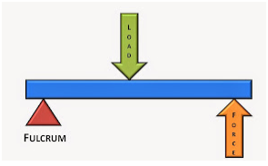
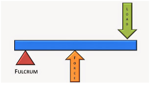
o Description: A rigid bar that pivots on a fixed point called the fulcrum.4 Levers can amplify force or distance.5
o Application: Used for lifting heavy objects, prying, and cutting.
o Example: Crowbars, seesaws, scissors.6
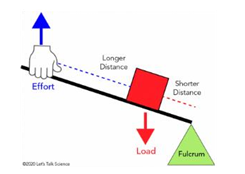
o Description: A flat surface tilted at an angle.7 It reduces the force required to move an object vertically by spreading the work over a longer distance.8
o Application: Moving heavy objects up ramps, sliding objects down slopes.
o Example: Ramps, screws (a screw is an inclined plane wrapped around a cylinder).9
o Description: Uses a screw thread to convert rotational motion into linear motion.10 It provides a large mechanical advantage for lifting heavy loads.11
o Application: Lifting vehicles for maintenance, adjusting machinery.
o Example: Car jacks, adjustable table legs.12
o Description: Uses pressurized fluid to transmit force and amplify it.13 Based on Pascal's principle.
o Application: Lifting heavy machinery, pressing and forming metals.
o Example: Vehicle lifts, hydraulic presses, hydraulic brakes.14
o Description: Uses multiple pulleys and ropes to reduce the force required to lift a load. The mechanical advantage increases with the number of supporting ropes.
o Application: Lifting heavy objects in construction, cranes.
o Example: Block and tackle, cranes, elevators.15
o Description: Uses toothed wheels to transmit and modify rotational motion and torque. Gear systems can change speed, torque, or direction of rotation.16
o Application: Transmissions in vehicles, lifting mechanisms, machinery.
o Example: Vehicle gearboxes, power tools, watches.17
o Gear systems can be used to decrease rotational speed while increasing torque, and vise versa.18
Principle: Levers work by applying force at one point to move a load at another point, using a fulcrum as the pivot point. The position of the fulcrum, load, and effort determines the lever's class and its mechanical advantage.
Principle: Inclined planes reduce the force required to lift an object by spreading the work over a longer distance. The longer the incline, the less force is needed, but the distance travelled increases.
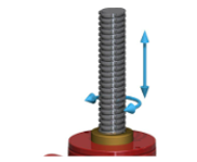
Principle: Screw jacks convert rotational motion into linear motion using a screw thread. The inclined plane of the thread acts as a wedge, allowing a small force applied to the handle to lift a heavy load.

Principle: Based on Pascal's principle, hydraulic systems transmit pressure equally throughout a fluid. A small force applied to a small piston can create a much larger force on a larger piston.
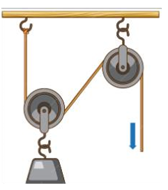
Principle: Pulleys redirect the force of the effort, allowing multiple ropes to support the load. Each additional rope reduces the force required to lift the load, increasing the mechanical advantage.

Principle: Gears with different sizes transmit rotational motion and torque. Smaller gears rotate faster but with less torque, while larger gears rotate slower but with more torque. This allows for speed and torque adjustments in machinery.
Mechanical Advantage (MA): The ratio of the output force (load) to the input force (effort). It indicates how much a machine multiplies the applied force.
Velocity Ratio (VR): The ratio of the distance moved by the effort to the distance moved by the load. It indicates how much the machine amplifies the distance moved.
Mechanical Efficiency (ME): The ratio of the output work to the input work. It represents the effectiveness of a machine in converting input energy into useful output work.
Key Formulas:
Example: A lever is used to lift a 500 N load. The effort applied is 100 N. The effort arm is 2 meters, and the load arm is 0.4 meters. Calculate MA, VR, and ME.
Key Formulas:
Example: A 2000 N box is pushed up a ramp 5 meters long to a height of 1 meter. The force required is 500 N. Calculate MA, VR, and ME.
Key Formulas:
Example: A screw jack with a handle length of 0.5 meters and a pitch of 0.005 meters is used to lift a 10,000 N load with an effort of 100 N. Calculate MA, VR, and ME.
Key Formulas:
Example: A hydraulic jack has an input piston area of 10 cm2 and an output piston area of 100 cm2. If a force of 50 N is applied to the input piston, calculate the force output.
Key Formulas:
Example: A pulley system with 4 supporting ropes is used to lift a 800 N load with an effort of 250 N. Calculate MA, VR, and ME.
Key Formulas:
Example: A gear system has a driving gear with 20 teeth and a driven gear with 60 teeth. Calculate the gear ratio.
Calculation: Gear ratios are typically given in the vehicle's specifications.
Example: A gearbox has the following ratios: 1st gear: 3.5:1, 2nd gear: 2.0:1, 3rd gear: 1.3:1, 4th gear: 1:1, 5th gear: 0.8:1. This means in first gear, the engine turns 3.5 times for every 1 turn of the output shaft.
Combined Ratios: To find the overall ratio, multiply the gearbox ratio by the final drive ratio.
Calculation: Steering box ratios are also given in vehicle specifications. They indicate how many degrees the steering wheel must turn to turn the wheels a certain degree.
Example: A steering box has a ratio of 16:1. This means the steering wheel must turn 16 degrees to turn the wheels 1 degree.
Calculation: The final drive ratio is the ratio between the ring gear and pinion gear in the differential.
Example: A final drive ratio of 4.10:1 means the pinion gear turns 4.10 times for every 1 turn of the ring gear.
Overall Ratio: The overall ratio is the product of the gearbox ratio and the final drive ratio.
Example: If a gearbox ratio is 3:1 and the final drive ratio is 4:1, the overall ratio is 12:1.
Question: A car has a gearbox ratio of 3:1 in first gear and a final drive ratio of 4:1. If the engine is turning at 3000 RPM, what is the speed of the drive wheels?
Heat is a form of energy transferred between objects or systems due to a temperature difference. It flows from a region of higher temperature to a region of lower temperature.
The SI unit of heat is the Joule (J).
Historically, the calorie (cal) was also used, where 1 calorie is the amount of heat required to raise the temperature of 1 gram of water by 1 degree Celsius. 1 calorie is approximately 4.186 joules.
Temperature is a measure of the average kinetic energy of the particles within a substance. It indicates the degree of hotness or coldness of an object or system.
| Feature | Heat | Temperature |
|---|---|---|
| Definition | Form of energy transferred due to temperature difference. | Measure of the average kinetic energy of particles. |
| Nature | Energy in transit. | A property of a substance. |
| Measurement | Measured in Joules (J) or calories (cal). | Measured in degrees Celsius (°C), Kelvin (K), or Fahrenheit (°F). |
| Transfer | Flows from hot to cold objects. | Does not flow; it is a state. |
| Quantity | Depends on the mass of the substance. | Independent of the mass of the substance. |
| Effect | Causes changes in temperature, phase, or volume. | Indicates the average kinetic energy of particles. |
| Example | The heat from a stove burner warms a pot of water. | The reading on a thermometer indicates the water's temperature. |
| Microscopic view | A measure of the total kinetic energy of the molecules in a substance. | A measure of the average kinetic energy of the molecules in a substance. |
o Explanation: When materials are heated, their particles vibrate more vigorously, causing them to move further apart.1 This results in an increase in the material's dimensions (length, area, or volume). Conversely, cooling causes contraction.
o Example:
o Explanation: Heat can cause materials to change their physical state (solid, liquid, or gas).4
o Example:
o Explanation: Heat can accelerate or initiate chemical reactions, leading to changes in the material's chemical composition.10
o Example:
o Explanation: Heating can cause materials to emit light (incandescence) or change their color due to alterations in their chemical structure.12
o Example:
o Explanation: Heat can induce electrical effects in materials, such as:
o Example:
o Expansion of engine components (pistons, cylinders) during operation.
o Expansion of brake rotors, potentially causing brake fade.
o Expansion of the metal body of the vehicle in hot weather.
o Fuel vaporization in the engine's combustion chamber.19
o Coolant boiling in the radiator due to overheating.20
o Melting of solder in electrical connections due to excessive current.
o Oxidation (rusting) of exhaust system components.21
o Degradation of engine oil due to high temperatures.22
o Combustion of fuel in the engine.23
o Exhaust manifolds glowing red-hot under heavy load.
o Paint fading due to prolonged exposure to sunlight and engine heat.
o Discoloration of brake rotors due to overheating.24
o Thermocouples used in engine temperature sensors.25
o Increased resistance in electrical wiring due to heat, potentially causing voltage drops.
o Overheating of electrical components causing them to fail.
o Description: Heat transfer through direct contact between particles of a material.1 Heat flows from hotter to colder regions.2
o Motor Vehicle Examples:
o Description: Heat transfer through the movement of fluids (liquids or gases).6 Hotter fluids rise, and colder fluids sink, creating convection currents.7
o Motor Vehicle Examples:
o Description: Heat transfer through electromagnetic waves. Does not require a medium.9
o Motor Vehicle Examples:
o Measurement: Conduction is not directly measured in the same way as temperature. Instead, we measure the rate of heat transfer through a material.
o Methods:
o In Motor Vehicles:
o Measurement: Temperature gauges on engines measure the temperature of the coolant or oil, providing an indirect indication of the engine's heat.16
o Types:
o Purpose:
Metric:
o Celsius (°C)
o Kelvin (K)
Imperial:
o Fahrenheit (°F)1
Celsius (°C) to Fahrenheit (°F):
o °F = (°C × 9/5) + 322
Celsius (°C) to Kelvin (K):
o K = °C + 273.15
Fahrenheit (°F) to Celsius (°C):
o °C = (°F - 32) × 5/9
Kelvin (K) to Celsius (°C):
o °C = K - 273.15
0 °C to °F:
o °F = (0 × 9/5) + 32 = 32 °F
0 °C to K:
o K = 0 + 273.15 = 273.15 K3
32 °F to °C:
o °C = (32 - 32) × 5/9 = 0°C
273.15 K to °C:
o °C = 273.15 - 273.15 = 0°C4
o A mercury-in-glass thermometer consists of a glass tube with a bulb at one end containing mercury.5
o The tube is sealed, and a scale is marked on the glass.
o When the thermometer is heated, the mercury expands and rises in the tube.
o When it cools, the mercury contracts and falls.6
o The height of the mercury column indicates the temperature.
o Accurate and reliable.
o Wide temperature range.
o Relatively inexpensive.
o Fragile.
o Contains mercury, which is toxic.
o Reading the measurement requires a direct line of sight.
o Low Temperature: Can thicken (waxing), leading to fuel flow problems and difficulty starting.
o High Temperature: Can decrease density, affecting fuel delivery and combustion.
o Low Temperature: Can reduce volatility, making starting difficult.
o High Temperature: Can vaporize excessively, leading to vapor lock and fuel delivery issues.
o Low Temperature: Reduces battery capacity and performance.7
o High Temperature: Can accelerate corrosion and electrolyte evaporation.
o Low Temperature: Can increase viscosity, affecting brake response.
o High Temperature: Can lead to boiling (vapor lock), causing brake failure.
o Low Temperature: Increases viscosity, reducing lubrication and increasing wear.
o High Temperature: Decreases viscosity, reducing lubrication and accelerating oxidation.8
o Low Temperature: Can freeze and damage the cooling system (hence the use of antifreeze).
o High Temperature: Can boil, leading to overheating and coolant loss.
o Power steering Fluid: Similar to other oils, lower temperatures thicken it, high temperatures thin it out.
o Windshield washer fluid: Should have an anti-freeze property to prevent freezing in cold climates.
o Description: A method used to measure the amount of heat involved in a physical or chemical process.1 It involves using a calorimeter, an insulated container, to measure heat exchange.2
o Procedure:
o Description: Used to determine the specific heat capacity of materials. A known amount of electrical energy is supplied to a material, and the resulting temperature change is measured.5
o Procedure:
o Description: Used to determine the latent heat of fusion or vaporization. The amount of heat required to change the phase of a substance is measured.
o Procedure:
o A larger mass requires more heat to achieve the same temperature change.8
o The amount of heat required to raise the temperature of 1 kg of a substance by 1 °C. Different materials have different specific heat capacities.9
o The greater the temperature change, the more heat is required.10
Principle: When two or more substances at different temperatures are mixed, heat will flow from the hotter substances to the colder substances until thermal equilibrium is reached (all substances have the same temperature).11
Heat Lost = Heat Gained: In an isolated system, the total heat lost by the hotter substances equals the total heat gained by the colder substances.
Calculations:
o Qlost = m1c1(T1 - Tf)
o Qgained = m2c2(Tf - T2)
o Where:
Question: 100 g of water at 80 °C is mixed with 200 g of water at 20 °C. Calculate the final temperature of the mixture. (Specific heat capacity of water is 4.186 J/g°C).
Working:
o Heat lost by hot water: Qlost = m1c1(T1 – Tf) = 100 g × 4.186 × (80 °C – Tf)
o Heat gained by cold water: Qgained = m2c2(Tf – T2) = 200 g × 4.186 × (Tf – 20 °C)
o Heat lost = Heat gained: 100(80 − Tf) = 200(Tf − 20)
o 8000 − 100Tf = 200Tf − 4000
o 12000 = 300Tf
o Tf = 40 °C
Answer: The final temperature is 40 °C.
Question: A 50 g piece of iron at 300 °C is dropped into 150 g of water at 20 °C. Calculate the final temperature of the mixture. (Specific heat capacity of iron is 0.45 J/g°C, water is 4.186 J/g°C).13
Working:
o Heat lost by iron: Qlost = 50 g × 0.45 J/g°C × (300 °C − Tf)
o Heat gained by water: Qgained = 150 g × 4.186 J/g°C × (Tf − 20 °C)
o Heat lost = Heat gained: 50 × 0.45 × (300 − Tf) = 150 × 4.186 × (Tf − 20)
o 6750 − 22.5Tf = 627.9Tf − 12558
o 19308 = 650.4Tf
o Tf ≈ 29.7 °C
Answer: The final temperature is approximately 29.7 °C.
Question: How much heat is required to melt 200g of ice at 0°C into water at 0°C? (Latent heat of fusion of ice is 334 J/g).
Working:
o Q = mL
o Q = 200g × 334 J/g
o Q = 66800J or 66.8kJ
Answer: 66.8kJ of heat is required.
A change of state, also known as a phase transition, is a physical process in which a substance transitions from one state of matter (solid, liquid, or gas) to another.
These changes occur due to the addition or removal of heat energy, which affects the kinetic energy of the particles within the substance.
o Melting: Solid to liquid (e.g., ice to water).
o Freezing (Solidification): Liquid to solid (e.g., water to ice).
o Vaporization (Boiling/Evaporation): Liquid to gas (e.g., water to steam).
o Condensation: Gas to liquid (e.g., steam to water).
o Sublimation: Solid to gas (e.g., dry ice to carbon dioxide gas).
o Deposition (Desublimation): Gas to solid (e.g., water vapor to frost).
o Sensible heat is the heat energy that causes a change in the temperature of a substance without changing its state.
o It is the heat we can "sense" because it results in a temperature change.
o It can be calculated using the formula: Q = mcΔT (where Q is heat, m is mass, c is specific heat capacity, and ΔT is temperature change).
o Latent heat is the heat energy that causes a change in the state of a substance without changing its temperature.
o It is the energy required to break or form intermolecular bonds during a phase transition.
o There are two types of latent heat:
o It can be calculated using the formula: Q = mL (where Q is heat, m is mass, and L is the latent heat).
Question: How much heat is required to melt 500 g of ice at 0 °C into water at 0 °C? (Latent heat of fusion of ice is 334 J/g).
Working:
o Q = mL
o Q = 500 g × 334 J/g
o Q = 167,000 J or 167 kJ
Answer: 167 kJ of heat is required.
Question: How much heat is required to vaporize 200 g of water at 100 °C into steam at 100 °C? (Latent heat of vaporization of water is 2260 J/g).
Working:
o Q = mL
o Q = 200 g × 2260 J/g
o Q = 452,000 J or 452 kJ
Answer: 452 kJ of heat is required.
Question: How much heat is required to convert 100 g of ice at -10 °C into steam at 100 °C? (Specific heat capacity of ice is 2.1 J/g°C, water is 4.186 J/g°C. Latent heat of fusion of ice is 334 J/g, latent heat of vaporization of water is 2260 J/g).
Working:
Answer: 303.36 kJ of heat is required.
Explanation: In this problem, we need to account for each step the water takes, temperature change of the ice, phase change of the ice, temperature change of the water, and finally the phase change of the water into steam.
o Expansion: When heated, the particles in a solid vibrate more vigorously, increasing the average distance between them. This causes the solid to expand in all dimensions (length, area, and volume).
o Contraction: When cooled, the particles vibrate less, decreasing the average distance between them, causing the solid to contract.
o Stress: If a solid is constrained while being heated or cooled, it can experience significant stress due to its inability to expand or contract freely.
o Expansion: Liquids also expand when heated, as the increased kinetic energy of the particles causes them to move further apart.1
o Contraction: Similarly, liquids contract when cooled.2
o Volume Change: Liquids primarily experience volume changes, as their shape is determined by the container.3
o Density Change: Since the mass remains constant, the change in volume results in a change in density. Hotter liquids are less dense than colder liquids.
o The fractional change in length per degree Celsius (°C) or Kelvin (K) change in temperature.5
o Formula: α = (ΔL / L0) / ΔT
o The fractional change in area per degree Celsius (°C) or Kelvin (K) change in temperature.7
o Formula: β = (ΔA / A0) / ΔT
o β is approximately 2α.
o The fractional change in volume per degree Celsius (°C) or Kelvin (K) change in temperature.
o Formula: γ = (ΔV / V0) / ΔT
o γ is approximately 3α.
Question: A steel rod with an original length of 2 meters is heated from 20 °C to 100 °C. The coefficient of linear expansion for steel is 12 × 10-6 /°C.12 Calculate the change in length.
Working:
o ΔL = αL₀ΔT
o ΔL = (12 × 10-6 /°C) × 2 m × (100 °C - 20 °C)
o ΔL = (12 × 10-6) × 2 × 80
o ΔL = 0.00192 m or 1.92 mm
Answer: The change in length is 1.92 mm.
Question: A square aluminum plate with an original area of 0.5 m² is heated from 15 °C to 80 °C. The coefficient of linear expansion for aluminum is 24 × 10-6 /°C. Calculate the change in area.
Working:
o β = 2α = 2 × (24 × 10-6 /°C) = 48 × 10-6 /°C
o ΔA = βA₀ΔT
o ΔA = (48 × 10-6 /°C) × 0.5 m² × (80 °C − 15 °C)
o ΔA = (48 × 10-6) × 0.5 × 65
o ΔA = 0.00156 m²
Answer: The change in area is 0.00156 m².
Question: A brass cube with an original volume of 0.1 m³ is heated from 25 °C to 125 °C. The coefficient of linear expansion for brass is 19 × 10-6 /°C.13 Calculate the change in volume.
Working:
o γ = 3α = 3 × (19 × 10-6 /°C) = 57 × 10-6 /°C
o ΔV = γV₀ΔT
o ΔV = (57 × 10-6 /°C) × 0.1 m³ × (125 °C − 25 °C)
o ΔV = (57 × 10-6) × 0.1 × 100
o ΔV = 0.00057 m³
Answer: The change in volume is 0.00057 m³.
Materials have different coefficients of thermal expansion, meaning they expand or contract at different rates when subjected to temperature changes.12
o Aluminum: High coefficient of linear expansion (around 23-24 × 10-6 /°C).3
o Plastics: Generally have high expansion rates, varying with the type.
o Brass: Moderate coefficient of linear expansion (around 19 × 10-6 /°C).4
o Copper: moderate coefficient of linear expansion(around 17 × 10-6 /°C)5
o Steel: Lower coefficient of linear expansion (around 11-12 × 10-6 /°C).6
o Invar: Very low coefficient of linear expansion (near zero in certain temperature ranges).
o Ceramics: generally have low expansion rates.
When selecting materials for vehicles, it's crucial to consider their expansion rates to prevent issues like:
Thermal Stress: Mismatched expansion can cause stress and cracking.7
Component Fit: Changes in size can affect the fit and function of components.
Seal Integrity: Expansion and contraction can compromise seals.8
o Pistons: Often made of aluminum alloys for lightweight, but careful design is needed to account for high thermal expansion.
o Cylinder Heads: Often made of aluminum or cast iron, with careful design to manage thermal stress.9
o Gaskets: Made from materials that can withstand temperature changes and maintain a seal.10
o Brake Rotors: Made of cast iron or steel, which have moderate expansion rates.
o Brake Lines: Made from flexible materials that can accommodate thermal expansion and vibration.
o Steel or aluminum panels: Used for body panels, with designs that allow for thermal expansion.
o Plastic body panels: Must be designed with expansion in mind, and often are not rigidly affixed to metal frames.
o Copper wires: Used for electrical wiring, with insulation that can withstand temperature changes.11
o Radiator: Often made with aluminium cores, and plastic or metal end tanks.12 The design must allow for expansion of the coolant, and the different expansion rates of the materials.
o Bearings pressed into housings: The housing is heated to expand it, and the bearing is inserted. As the housing cools, it contracts, creating a tight fit.
o Cylinder liners inserted into engine blocks: Similar to bearings, the engine block is heated, and the liner is inserted.
o Valve seat inserts: The cylinder head is heated, and the valve seat is inserted.13
o Gears or pulleys fitted onto shafts: The gear or pulley is heated to expand it, and it's placed onto the shaft. As it cools, it shrinks, creating a tight fit.
o Connecting rod small end bushings: The connecting rod is heated, and the bushing is inserted.
o Electrical connections: Heat-shrink tubing is placed over electrical connections and heated to shrink it, providing insulation and protection.14
o Some plastic components are designed with snap fits that take advantage of the materials flexibility, and slight thermal expansion.15