
LEARNING OUTCOME 1: DESIGN DATABASE
Designing a Database
A well-designed database is like a well-organized library—it provides users with the information they need in an accessible and understandable way. The design process begins with understanding the end-users and their requirements.
1. Identifying Your End Users: Who Needs This Information?
The first step is to identify everyone who will use the database. These end-users can be internal (e.g., Sales, Marketing, Finance departments) or external (e.g., customers using a website). Each group has specific needs; for example, a salesperson needs customer contact info, while a manager needs sales trend reports.
2. End User Views: Shaping How Users See the Data
Next, define what information is crucial for each user group and how they will interact with it. This involves creating different "views" of the data. A salesperson doesn't need to see engineering specs. This step helps in designing user-friendly interfaces, such as dashboards for managers or simple search forms for customer service.
3. Specifying Outputs: Delivering Information in the Right Format
Determine the format in which data will be presented. Sales managers might require comprehensive reports with charts, while customer service representatives might need a simple screen displaying customer details. The output must be clear, concise, and tailored to the user's role.
4. Analysing Transaction Processing Requirements
Understand the actions users will perform on the data. These are known as transaction processing requirements and often involve CRUD operations (Create, Read, Update, and Delete). For example, users may need to add new customers, retrieve order details, or update product prices. Analyzing these requirements ensures the database has the necessary functionality.
Entities: Building Blocks of Your Database
Entities are the fundamental concepts or objects you want to store information about. They are the nouns in your data's description.
- Real-World Objects: Entities represent key things you want to track, like "Products," "Customers," and "Orders."
- Characteristics: A good entity is well-defined, has independent existence, and each instance (e.g., each customer) is uniquely identifiable.
Attributes: Defining the Details of Your Entities
Attributes are the specific properties that describe an entity. They are the adjectives that give detail to your entities.
- Describing Entities: For a "Customer" entity, attributes could be "customer_name," "email_address," and "phone_number."
- Characteristics: A good attribute is atomic (indivisible, like splitting "address" into street, city, state) and relevant to the entity.
Candidate, Primary, and Alternate Keys
Keys are unique identifiers for records in a database table.
- Candidate Key: A minimal set of attributes that uniquely identifies an entity instance. A table can have multiple candidate keys.
- Primary Key: The chosen candidate key that serves as the main unique identifier for a table. It cannot contain null values.
- Alternate Key: Any candidate key that was not chosen to be the primary key.
Drawing ER Models (ERDs)
Entity-Relationship Diagrams (ERDs) are visual blueprints of a database. They depict entities (rectangles), their attributes, and the relationships between them (diamonds and lines).
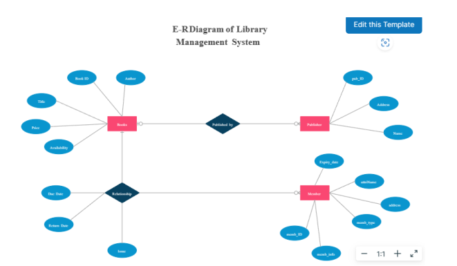
This diagram shows entities like "Book," "Author," and "Loan" and illustrates their relationships and attributes, helping to visualize the database structure.
Minimizing Redundancy and Validating the Model
After the initial design, it's crucial to refine the model.
- Check for Redundancy: Eliminate data duplication to save space, prevent inconsistencies, and simplify maintenance. This is often achieved through a process called normalization.
- Validate Against User Transactions: Simulate user actions (CRUD operations) to ensure the model supports all necessary transactions efficiently.
- Review the Conceptual Model: Present the ERD and model to stakeholders and end-users for feedback to ensure it accurately meets their needs.
Evaluating Database Models and Choosing a DBMS
Choosing the right Database Management System (DBMS) is a critical step. The decision should be based on:
- Pricing: Compare costs of open-source (e.g., MySQL, PostgreSQL) versus commercial options (e.g., Oracle, SQL Server).
- Migration: If migrating from an existing system, assess the ease of data transfer to the new DBMS.
- Functionality: Ensure the DBMS supports the features required for your business needs.
- Scalability: Consider if the DBMS can handle future growth in data volume and user load.
Database Normalization
Normalization is a systematic process of organizing tables to reduce data redundancy and improve data integrity. The main objectives are:
- Reduce Data Redundancy: Store each piece of data only once.
- Enhance Data Integrity: Ensure data is accurate and consistent.
- Simplify Data Manipulation: Make it easier to insert, update, and delete data without causing anomalies.
Normalization is achieved through a series of levels called Normal Forms (NF):
- First Normal Form (1NF): Ensures that the table has a primary key and eliminates duplicate rows.
- Second Normal Form (2NF): Meets 1NF and removes partial dependencies, where an attribute depends on only part of a composite primary key.
- Third Normal Form (3NF): Meets 2NF and removes transitive dependencies, where an attribute depends on another non-key attribute.
Building Entity Relationships: Strong vs. Weak
- Strong Entities: Have their own primary key and can exist independently (e.g., a "Customer" can exist without placing an "Order").
- Weak Entities: Depend on a strong entity for their existence and do not have a primary key of their own. Their identifier is formed by combining the primary key of the owner (strong) entity with its own partial identifier (e.g., "Order_Detail" depends on an "Order").
File Organization and Access Methods
This refers to how data is physically arranged on a storage device, which affects retrieval speed.
- Heap (Unordered): Records are placed in no particular order. Fast for insertions, but slow for searching.
- Sequential: Records are stored in a specific order based on a key field. Efficient for processing records in sequence.
- Indexed: Uses an index (like in a book) to quickly locate records without searching the entire file.
- Hashed: Uses a hash function to calculate a record's address, providing very fast direct access.