To place networking equipment in strategic positions in line with network design, you must first interpret the network designs.
This includes understanding the following:
The topology of the network: This refers to the physical layout of the network, such as whether it is a bus, star, or ring topology.
The types of devices on the network: This includes devices such as switches, routers, and firewalls.
The bandwidth requirements of the network: This is the amount of data that needs to be transmitted over the network at any given time.
The security requirements of the network: This includes measures to protect the network from unauthorized access and attacks.
Once you have a good understanding of the network designs, you can begin to plan where to place the networking equipment.
Here’s how:
Place switches and routers in central locations:
Switches and routers are the backbone of any network. They are responsible for routing data between different devices on the network. By placing switches and routers in central locations, you can minimize the distance that data needs to travel. This will improve performance and reduce latency.
To place switches and routers in central locations, you need to identify the areas of the network where there is the most traffic. These areas are typically the places where people are most likely to be using the network, such as in offices, classrooms, and common areas.
Place firewalls at the edge of the network:
Firewalls are responsible for protecting the network from unauthorized access and attacks. By placing firewalls at the edge of the network, you can create a barrier between the network and the internet. This will help to protect the network from malicious traffic.
To place firewalls at the edge of the network, you need to identify the points where the network connects to the internet. These points are typically the places where the network router is located.
Place wireless access points in areas where there is a high demand for wireless connectivity:
Wireless access points allow devices to connect to the network wirelessly. By placing wireless access points in areas where there is a high demand for wireless connectivity, you can ensure that all users have a good signal.
To place wireless access points in areas where there is a high demand for wireless connectivity, you need to identify the areas where people are most likely to be using wireless devices, such as in offices, classrooms, and common areas. You also need to consider the layout of the building and the location of any obstacles that may interfere with the wireless signal.
Consider the physical environment:
Make sure to place the networking equipment in areas where it is protected from dust, moisture, and extreme temperatures.
Here are some specific examples of how to place networking equipment in strategic positions:
In a small office, you might place a switch in the center of the office and connect all of the computers to the switch. You could then place a firewall at the edge of the network, between the office and the internet.
In a larger office, you might have multiple switches and routers. The switches would be placed in central locations on each floor of the office, and the routers would be used to connect the switches together. You would still place a firewall at the edge of the network, between the office and the internet.
In a school, you might have multiple switches and routers in different parts of the building. The switches would be placed in central locations on each floor of the building, and the routers would be used to connect the switches together. You might also have wireless access points in different areas of the building, such as classrooms, libraries, and cafeterias.
In a data center, you might have multiple racks of networking equipment. The switches and routers would be placed in the racks, and the firewalls would be placed at the edge of the network, between the data center and the internet.
How these help improve performance, security, and reliability:
Performance: By placing switches and routers in central locations and wireless access points in areas where there is a high demand for wireless connectivity, you can minimize the distance that data needs to travel and improve performance.
Security: By placing firewalls at the edge of the network, you can create a barrier between the network and the internet and protect the network from unauthorized access and attacks.
Reliability: By placing networking equipment in central locations and away from obstacles, you can reduce the risk of outages and ensure that the network is reliable.
568A and 568B WIRING STANDARDS
THE 568A wiring standard is a color-coding scheme for wiring twisted-pair Ethernet cables. It is one of the two most common wiring standards, along with 568B.
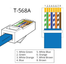
The 568A Wiring Standard
The 568A wiring standard is defined by the Telecommunications Industry Association (TIA) and the Electronics Industries Alliance (EIA). It is also known as the T568A standard.
Color-Coding Scheme
Pin 1: White/Green
Pin 2: Green
Pin 3: White/Orange
Pin 4: Blue
Pin 5: White/Blue
Pin 6: Orange
Pin 7: White/Brown
Pin 8: Brown
Wiring an Ethernet Cable
To wire an Ethernet cable using the 568A wiring standard, simply strip the outer jacket of the cable about 1 inch from the end, untwist the pairs of wires and straighten them out, arrange the wires in the correct pinout order, insert the wires into an RJ-45 connector, and crimp the connector using a crimping tool.
Applications
The 568A wiring standard is used in a variety of applications, including:
Residential networks
Commercial networks
Government networks
Educational networks
Industrial networks
Benefits
The 568A wiring standard is a reliable and versatile wiring standard that can be used in a wide range of applications. Here are some of the benefits of using the 568A wiring standard:
It is widely supported by network devices and equipment.
It is relatively easy to implement.
It is reliable and provides good performance.
It is compatible with both 100BASE-T and 1000BASE-T Ethernet networks.
The 568B Wiring Standard
THE 568B wiring standard is a color-coding scheme for wiring twisted-pair Ethernet cables. It is one of the two most common wiring standards, along with 568A.
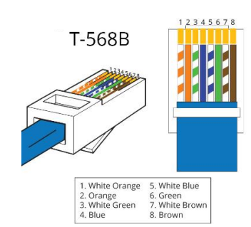
The 568B Wiring Standard
The 568B wiring standard is defined by the Telecommunications Industry Association (TIA) and the Electronics Industries Alliance (EIA). It is also known as the T568B standard.
Color-Coding Scheme
Pin 1: White/Orange
Pin 2: Orange
Pin 3: White/Green
Pin 4: Blue
Pin 5: White/Blue
Pin 6: Green
Pin 7: White/Brown
Pin 8: Brown
Wiring an Ethernet Cable
To wire an Ethernet cable using the 568B wiring standard, simply strip the outer jacket of the cable about 1 inch from the end, untwist the pairs of wires and straighten them out, arrange the wires in the correct pinout order, insert the wires into an RJ-45 connector, and crimp the connector using a crimping tool.
Applications of the 568B Wiring Standard
Residential networks
Commercial networks
Government networks
Educational networks
Industrial networks
Benefits of Using the 568B Wiring Standard
It is widely supported by network devices and equipment.
It is relatively easy to implement.
It is reliable and provides good performance.
It is compatible with both 100BASE-T and 1000BASE-T Ethernet networks.
Which Wiring Standard Should I Use?
The 568B wiring standard is the most widely used wiring standard for Ethernet cables. However, the 568A wiring standard is still used in some cases, such as when connecting to older equipment or when required by specific regulations.
If you are unsure which wiring standard to use, it is always best to consult with the documentation for your network devices and equipment.
How to Test an Ethernet Cable
Once you have terminated an Ethernet cable, it is important to test it to make sure that it is working properly. There are a few different ways to test an Ethernet cable.
One way to test an Ethernet cable is to connect it to two devices and try to transfer data between the devices. If the data transfers successfully, then the cable is working properly.
Another way to test an Ethernet cable is to use a cable tester. Cable testers can be purchased at most electronics stores.
To use a cable tester, simply connect the cable to the tester and press the test button. The tester will then check the cable for any problems. If the cable is working properly, the tester will indicate that the cable is good.
If the cable tester indicates that the cable is bad, then you will need to terminate the cable again or replace the cable.
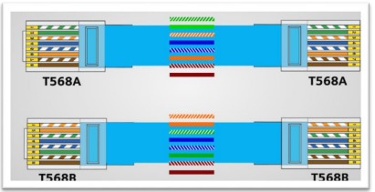
Straight Through Cable
What do you need to know about straight-through cable termination?
To terminate a straight-through cable, you will need the following:
A straight-through Ethernet cable
An RJ-45 connector
A crimping tool
You will also need to know the pinout order for a straight-through cable.
Pin
Color
1
White/Green
2
Green
3
White/Orange
4
Blue
5
White/Blue
6
Orange
7
White/Brown
8
Brown
How to terminate a straight-through cable:
Strip the outer jacket of the Ethernet cable about 1 inch from the end.
Untwist the pairs of wires and straighten them out.
Arrange the wires in the correct pinout order.
Insert the wires into the RJ-45 connector, making sure that each wire is inserted into the correct pin.
Crimp the RJ-45 connector using the crimping tool.
Repeat steps 1-5 for the other end of the Ethernet cable.
Once you have terminated both ends of the Ethernet cable, you can connect it to your devices.
Tips for terminating a straight-through cable:
Make sure that the wires are untwisted and straightened out before you insert them into the RJ-45 connector. This will help to ensure a good connection.
Be careful not to over-crimp the RJ-45 connector. Over-crimping can damage the connector and make it unusable.
If you are unsure how to terminate a straight-through cable, you can find many tutorials online or in networking books.
CROSS OVER CABLE TERMINATION
What is crossover cable termination?
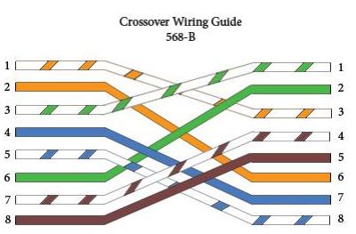
Crossover cable termination is the process of connecting the wires of an Ethernet cable to an RJ-45 connector in a specific order, but in a different order at each end of the cable. Crossover cables are used to connect two devices that are on different networks, such as two computers directly or a switch to a router.
What do you need to know about crossover cable termination?
To terminate a crossover cable, you will need the following:
A crossover Ethernet cable
An RJ-45 connector
A crimping tool
You will also need to know the pinout order for a crossover cable. The pinout order is as follows:
Pin
Left End
Right End
1
White/Green
White/Orange
2
Green
Orange
3
White/Orange
White/Green
4
Blue
Blue
5
White/Blue
White/Blue
6
Orange
Green
7
White/Brown
White/Brown
8
Brown
Brown
How to terminate a crossover cable:
1. Strip the outer jacket of the Ethernet cable about 1 inch from the end. 2. Untwist the pairs of wires and straighten them out. 3. Arrange the wires in the correct pinout order for the left end of the cable. 4. Insert the wires into the RJ-45 connector, making sure that each wire is inserted into the correct pin. 5. Crimp the RJ-45 connector using the crimping tool. 6. Repeat steps 1-5 for the other end of the Ethernet cable, but using the pinout order for the right end of the cable.
Once you have terminated both ends of the Ethernet cable, you can connect it to your devices.
Tips for terminating a crossover cable:
• Make sure that the wires are untwisted and straightened out before you insert them into the RJ-45 connector. This will help to ensure a good connection. • Be careful not to over-crimp the RJ-45 connector. Over-crimping can damage the connector and make it unusable. • If you are unsure how to terminate a crossover cable, you can find many tutorials online or in networking books.
Note: Most modern network devices support Auto-MDIX, which means they can automatically detect whether a straight-through or crossover cable is needed and configure themselves accordingly. However, crossover cables may still be needed in some situations, such as when connecting two older devices or when troubleshooting network problems.
ETHERNET DEPLOYMENT STANDARDS
Ethernet deployment standards are a set of guidelines that define how to install and configure Ethernet networks in a way that is reliable, efficient, and secure. These standards are developed by the Institute of Electrical and Electronics Engineers (IEEE) and are widely accepted by the networking industry.
Some of the most important Ethernet deployment standards include:
• IEEE 802.3: This standard defines the physical and data link layer specifications for Ethernet networks. It includes specifications for the different types of Ethernet media, such as twisted pair copper cable, coaxial cable, and fiber optic cable. • IEEE 802.1Q: This standard defines the VLAN (virtual LAN) protocol. VLANs allow you to divide your network into multiple logical segments, even if all of the devices on the network are physically connected to the same switch or router. • IEEE 802.1x: This standard defines the EAP (Extensible Authentication Protocol) framework. EAP provides a way to authenticate users and devices before they are granted access to the network. • IEEE 802.3ad: This standard defines the LACP (Link Aggregation Control Protocol). LACP allows you to combine multiple physical links into a single logical link, which can improve performance and reliability. • IEEE 802.3af/at/bt: These standards define the Power over Ethernet (PoE) protocols. PoE allows you to transmit power over Ethernet cables, which can be useful for powering devices such as wireless access points and IP cameras.
When designing and deploying an Ethernet network, it is important to follow these standards to ensure that your network is reliable, efficient, and secure.
Here are some additional tips for deploying an Ethernet network:
• Use high-quality cabling and connectors. This will help to reduce the risk of errors and outages. • Properly label all of your cables and devices. This will make it easier to troubleshoot problems. • Use a network diagram to document your network topology. This will help you to understand how your network works and to plan for future growth. • Regularly test your network for errors and performance problems. This will help you to identify and fix problems early on. • Implement security measures to protect your network from unauthorized access and attacks. This may include using firewalls, intrusion detection systems, and access control lists.
CONFIGURE NETWORK DEVICES
IP Addressing (IPv4, IPv6)
To set up IPv4 and IPv6 on your network, you will need to configure your network devices and your computers.
Configure your network devices
The first step is to configure your network devices, such as your router and switch. To do this, you will need to access the device's administration console. This can usually be done by connecting to the device's web interface or by using a terminal emulator program.
Once you have accessed the device's administration console, you will need to locate the settings for IP addressing. The specific steps involved will vary depending on the make and model of the device, but most devices will have a section dedicated to IP addressing.
To configure IPv4 addressing, you will need to specify the following information:
• IP address: This is the unique address that will be assigned to the device on the network. • Subnet mask: This is a bitmask that is used to determine which IP addresses are on the same network as the device. • Gateway address: This is the address of the router or other device that the device will use to access the internet.
To configure IPv6 addressing, you will need to specify the following information:
• IPv6 address: This is the unique address that will be assigned to the device on the network. • Prefix length: This is a value that determines how many bits of the IPv6 address are used to identify the network. • Gateway address: This is the address of the router or other device that the device will use to access the internet.
Once you have configured the IP addressing settings, you will need to save the changes and restart the device.
Configure your computers
Once you have configured your network devices, you need to configure your computers. To do this, you will need to access the network settings on each computer. The specific steps involved will vary depending on the operating system that you are using, but most operating systems will have a section dedicated to network settings.
To configure IPv4 addressing on a computer, you will need to specify the following information:
• IP address: This is the unique address that will be assigned to the computer on the network. • Subnet mask: This is a bitmask that is used to determine which IP addresses are on the same network as the computer. • Gateway address: This is the address of the router or other device that the computer will use to access the internet.
To configure IPv6 addressing on a computer, you will need to specify the following information:
• IPv6 address: This is the unique address that will be assigned to the computer on the network. • Prefix length: This is a value that determines how many bits of the IPv6 address are used to identify the network. • Gateway address: This is the address of the router or other device that the computer will use to access the internet.
Once you have configured the IP addressing settings, you will need to save the changes and restart the computer.
Test your configuration
Once you have configured your network devices and computers, you should test your configuration to make sure that everything is working properly. To do this, you can try to ping other devices on your network and try to access the internet.
If you are having problems, you can try troubleshooting your network. You can also consult the documentation for your network devices and computers for more information.
Additional tips
• Make sure that you have the correct administrative credentials for your network devices and computers before you try to configure them. • Be careful when changing network settings. Incorrect settings can cause devices to become inaccessible or to disrupt the network. • If you are unsure how to configure a particular setting, consult the documentation for your network devices and computers. • If you are having problems, you can try troubleshooting your network or contacting your network administrator for assistance.
NAT, PAT, SNAT, DNAT
NAT, PAT, SNAT, and DNAT are all forms of network address translation (NAT), which is a technique used to translate between private and public IP addresses. Private IP addresses are not routable on the public internet, while public IP addresses are.
NAT is used to allow devices on a private network to access the public internet. When a device on a private network sends a packet to the internet, the NAT device translates the private IP address of the device to a public IP address. The packet is then forwarded to the internet using the public IP address.
Static NAT
Static NAT is the simplest type of NAT. It maps a single private IP address to a single public IP address. This is typically used for servers that need to be accessible from the internet, such as web servers and mail servers.
To set up static NAT, you will need to configure your router or firewall to map the private IP address of the server to the public IP address that you want to use. You will also need to configure the server to use the static NAT IP address as its default gateway.
Dynamic NAT
Dynamic NAT is the most common type of NAT. It maps a pool of private IP addresses to a pool of public IP addresses. This is typically used for home networks and small businesses.
To set up dynamic NAT, you will need to configure your router or firewall to use a range of private IP addresses and a range of public IP addresses. The router will then automatically map the private IP addresses to the public IP addresses as needed.
Port Address Translation (PAT)
PAT is a type of NAT that maps a single public IP address to multiple private IP addresses using different ports. This is typically used for home networks and small businesses with a limited number of public IP addresses.
To set up PAT, you will need to configure your router or firewall to use a single public IP address and a range of private IP addresses. The router will then automatically map the private IP addresses to the public IP address using different ports.
Destination NAT (DNAT)
DNAT is a type of NAT that translates the destination IP address of a packet. This is typically used for port forwarding, which allows incoming connections to be routed to a specific device on the private network.
To set up DNAT, you will need to configure your router or firewall to map the public IP address and port that you want to use to the private IP address and port of the device on your network that you want to receive the incoming connections.
ROUTING
Routing is the process of forwarding network packets from one network to another. There are two main types of routing: static and dynamic.
Static Routing
Static routing is a manual process in which the network administrator manually configures the routing table on each router in the network. The routing table contains a list of all the networks that the router can reach, as well as the path to each network.
Dynamic Routing
Dynamic routing is an automated process in which the routers in the network learn about the network topology by exchanging routing information with each other. This allows the routers to dynamically update their routing tables without the need for manual intervention by the network administrator.
Advantages of Static Routing:
Simple to configure and manage
More secure than dynamic routing
More predictable performance
Disadvantages of Static Routing:
Requires manual configuration and management
Can be difficult to scale to large networks
Can be difficult to troubleshoot
Advantages of Dynamic Routing:
Automated configuration and management
Scales well to large networks
Easier to troubleshoot
Disadvantages of Dynamic Routing:
More complex to configure and manage than static routing
Less secure than static routing
Less predictable performance
Which Type of Routing Should You Use?
The best type of routing to use depends on the specific needs of your network. If you have a small network with simple requirements, then static routing may be the best option for you. However, if you have a large network or complex requirements, then dynamic routing is likely the better option.
General Guidelines for Choosing Between Static and Dynamic Routing:
Use static routing for small networks with simple requirements.
Use dynamic routing for large networks or networks with complex requirements.
Use static routing for networks that require high security or predictable performance.
Use dynamic routing for networks that require automated configuration and management.
TEST NETWORK CONNECTIVITY
PHYSICAL LAYER
To test network connectivity at the physical layer, you can use a cable tester. A cable tester is a device that can test the integrity of a network cable and identify any problems with the cable.
To use a cable tester, simply connect the tester to the two ends of the network cable. The tester will then send a signal through the cable and test the signal strength and quality. If the cable is good, the tester will indicate that the cable is passing. However, if the cable is bad, the tester will indicate that the cable is failing.
If the cable tester indicates that the cable is failing, you will need to replace the cable. Alternatively, you can try to repair the cable if the damage is minor.
Additional Tips for Testing Network Connectivity at the Physical Layer:
Make sure that the network cable is properly connected to both devices.
Check the network cable for any damage, such as kinks or breaks.
If you are using a long network cable, consider using a signal booster to improve the signal strength.
If you are still having problems with network connectivity, try replacing the network cable with a shorter cable.
NETWORK LAYER
To test network connectivity at the network layer, you can use the ping command. The ping command is a utility that sends a series of packets to a specified IP address and then waits for the packets to be returned. If the packets are returned, then the ping command will indicate that the network connection is working properly. However, if the packets are not returned, then the ping command will indicate that the network connection is not working properly.
To use the ping command, simply open a terminal window and type the following command:
ping <IP address>
Replace <IP address> with the IP address of the device that you want to test the network connection to. For example, to test the network connection to your router, you would type the following command:
ping 192.168.1.1
If the network connection is working properly, then the ping command will return a series of replies. Each reply will include the following information:
The round-trip time (RTT) of the packet, which is the time it took for the packet to be sent and returned.
The time to live (TTL) of the packet, which is the number of routers that the packet can pass through before it is discarded.
The sequence number of the packet.
If the network connection is not working properly, then the ping command will either return a message indicating that the destination is unreachable or it will time out.
Additional Tips for Testing Network Connectivity at the Network Layer:
Make sure that the IP address of the device that you are testing is correct.
Check the network cable for any damage, such as kinks or breaks.
If you are using a firewall, make sure that the ping command is allowed to pass through the firewall.
If you are still having problems with network connectivity, try restarting the router and the device that you are testing.
INTERPRET RESULTS OF NETWORK CONNECTIVITY TESTS
The results of network connectivity tests can be interpreted to determine whether a network connection is working properly and to identify any problems with the network.
Physical Layer Tests
Physical layer tests, such as cable tests, can be used to identify problems with the physical infrastructure of the network, such as damaged or faulty cables. If a cable test fails, it means that the cable is not working properly and needs to be repaired or replaced.
Network Layer Tests
Network layer tests, such as ping tests, can be used to identify problems with the routing and forwarding of packets on the network. If a ping test fails, it means that the destination device is not reachable. This could be due to a number of factors, such as a misconfiguration, a firewall blocking traffic, or a problem with the destination device itself.
Interpreting Test Results
When interpreting the results of network connectivity tests, it is important to consider the following factors:
The type of test that was performed: Different tests can identify different types of problems. For example, a cable test can only identify problems with the physical infrastructure of the network, while a ping test can only identify problems with the routing and forwarding of packets.
The results of all of the tests that were performed: By looking at the results of all of the tests that were performed, you can get a better understanding of the overall health of the network and the source of any problems.
The network topology: The network topology can also help you to interpret the results of network connectivity tests. For example, if you are testing a network with multiple subnets, you may need to perform additional tests to verify that the routers are forwarding packets correctly between the subnets.
If you are unsure how to interpret the results of network connectivity tests, you should consult with a network engineer or other qualified professional.
Examples of Interpreting Results of Common Network Connectivity Tests:
Ping test: If the ping test is successful, it means that the destination device is reachable and that the routing and forwarding of packets on the network is working properly. If the ping test fails, it means that the destination device is not reachable. This could be due to a number of factors, such as a misconfiguration, a firewall blocking traffic, or a problem with the destination device itself.
Traceroute test: A traceroute test can be used to identify the path that packets take between the source device and the destination device. If the traceroute test fails, it means that there is a problem with the routing or forwarding of packets on the network.
DNS lookup test: A DNS lookup test can be used to verify that the DNS server is working properly and that it is able to resolve domain names to IP addresses. If the DNS lookup test fails, it means that the DNS server is not working properly or that the domain name cannot be resolved.
By interpreting the results of network connectivity tests, you can identify and resolve problems with your network, which can help to improve the performance and reliability of your network.
GENERATE NETWORK DOCUMENTATION
WIRING AND PORT LOCATIONS
To develop network documentation for wiring and port locations, you can use a variety of methods, including:
Network diagram: A network diagram is a visual representation of your network topology. It shows the different devices on your network and how they are connected to each other. You can create a network diagram using a variety of tools, such as Visio, Lucidchart, or Draw.io.
Spreadsheet: A spreadsheet can be used to track the wiring and port locations on your network. You can create a spreadsheet with columns for the device name, port number, cable type, and cable length.
Database: A database can be used to manage your network documentation. You can create a database with tables for devices, ports, cables, and other information.
Once you have chosen a method for documenting your wiring and port locations, you need to collect the necessary information. This information can be collected by physically inspecting your network or by using network management software.
Once you have collected the necessary information, you can begin to create your network documentation. If you are using a network diagram, you will need to add the devices and cables to the diagram. If you are using a spreadsheet or database, you will need to enter the information into the appropriate tables.
Once your network documentation is complete, you should review it regularly to ensure that it is up-to-date. You should also make sure that your network documentation is accessible to everyone who needs it.
Additional Tips for Developing Network Documentation for Wiring and Port Locations:
Be consistent with your naming conventions. This will make it easier to find the information that you need.
Use clear and concise language. Avoid using technical jargon that your audience may not understand.
Include diagrams and screenshots to illustrate your documentation. This can help to make your documentation more visually appealing and easier to understand.
Review your documentation regularly and make updates as needed.
Here is an example of a network documentation table for wiring and port locations:
Device Name
Port Number
Cable Type
Cable Length
Router 1
1
Cat6
10m
Router 2
1
Cat6
10m
Switch 1
1
Cat6
10m
Switch 2
1
Cat6
10m
Switch 3
1
Cat6
10m
Switch 4
1
Cat6
10m
Computer 1
1
Cat6
5m
Computer 2
1
Cat6
5m
Computer 3
1
Cat6
5m
This table provides a clear and concise overview of the wiring and port locations on the network. It includes the name of each device, the port number, the cable type, and the cable length. This information can be used to troubleshoot network problems and to plan for future network changes.
In addition to the table, a network diagram can also be used to document wiring and port locations. A network diagram is a visual representation of the network topology. It shows the different devices on the network and how they are connected to each other.
A network diagram can be used to identify the path that packets take between the different devices on the network. It can also be used to identify any potential bottlenecks or chokepoints in the network.
By using a network diagram and a network documentation table, you can create a comprehensive and informative documentation of your network wiring and port locations. This documentation can be used to troubleshoot network problems, to plan for future network changes, and to provide information to other network administrators.
DEVELOP NETWORK DOCUMENTATION FOR PHYSICAL AND LOGICAL NETWORK DIAGRAMS
Steps to Develop Network Documentation
Identify your audience: Who will be using your network documentation? This will help you to determine the level of detail that you need to include in your documentation.
Collect the necessary information: This information can be collected by physically inspecting your network or by using network management software.
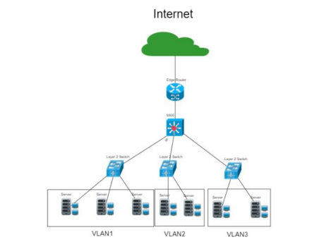
Physical network diagram:
A physical network diagram shows the physical layout of your network, including the location of devices, cables, and wiring. You can use a variety of tools to create a physical network diagram, such as:
Visio: A versatile diagramming tool.
Lucidchart: A web-based diagramming application.
Draw.io: A free online diagramming tool.
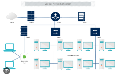
Logical Network Diagram
A logical network diagram shows the logical layout of your network, including the IP addresses, subnets, and routing information. You can use the same tools that you used to create your physical network diagram to create your logical network diagram.
Documentation Review
5. Review and update your documentation regularly. Network documentation should be reviewed and updated regularly to ensure that it is accurate and up-to-date.
Tips for Developing Network Documentation
Use clear and concise language: Avoid using technical jargon that your audience may not understand.
Use diagrams and screenshots: This can help to make your documentation more visually appealing and easier to understand.
Label all devices and cables: This will make it easier to identify specific devices and cables.
Use consistent naming conventions: This will make it easier to find the information that you need.
Include a legend: Include a legend in your diagrams to explain the symbols that you are using.
Store documentation centrally: Store your network documentation in a central location where it is accessible to everyone who needs it.
Labeling
Labeling is an important part of network documentation. Labels can be used to identify devices, cables, ports, and other network components. This can help to troubleshoot network problems, to plan for future network changes, and to provide information to other network administrators.
Tips for Labeling Network Components
Use clear and concise labels: Avoid using abbreviations or technical jargon that your audience may not understand.
Use a consistent labeling convention: This will make it easier to find the information that you need.
Label all devices and cables: This will make it easier to identify specific devices and cables.
Use easy-to-read labels: Avoid using small or difficult-to-read fonts.
Use durable labels: This will ensure that the labels remain legible over time.
Examples of Labeling Network Components
Devices: Label devices with their name and function. For example, you could label a router as "Router" and a switch as "Switch."
Cables: Label cables with their type and destination. For example, you could label a cable that connects a router to a switch as "Router to Switch Cable."
Ports: Label ports with their number and function. For example, you could label a port on a switch as "Port 1" and label a port on a computer as "Ethernet Port."
Methods for Labeling Network Components
Physical labels: Physical labels can be attached to devices and cables. Physical labels can be made of paper, vinyl, or other materials.
Software labels: Software labels can be used to label devices and cables in network management software. Software labels are typically easier to create and update than physical labels.
Automated labeling: Automated labeling solutions can be used to automatically label devices and cables. Automated labeling solutions can be used to save time and to ensure that labels are consistent and accurate.
Configuration Documentation
Configuration documentation is a record of the settings and configuration of network devices and software. It is an important part of network documentation, as it can help to troubleshoot network problems, to plan for future network changes, and to provide information to other network administrators.
Formats for Configuration Documentation
Text files
Spreadsheets
Databases
Network management software
Tips for Creating Configuration Documentation
Be comprehensive: Your configuration documentation should include all of the settings and configuration for your network devices and software.
Be organized: Your configuration documentation should be organized in a way that makes it easy to find the information that you need.
Be up-to-date: Your configuration documentation should be updated regularly to reflect changes to your network devices and software.
Be accessible: Your configuration documentation should be accessible to everyone who needs it.
Examples of Configuration Documentation
Device name
Device model
Device serial number
Device firmware version
Device IP address
Device subnet mask
Device gateway address
Device DNS server addresses
Device configuration settings
Software name
Software version
Software configuration settings
Tools for Creating Configuration Documentation
Text editors
Spreadsheets
Databases
Network management software
Additional Tips for Creating Configuration Documentation
Use clear and concise language: Avoid using technical jargon that your audience may not understand.
Include comments: Include comments in your configuration documentation to explain the purpose of each setting.
Use consistent naming conventions: This will make it easier to find the information that you need.
Review regularly: Review your configuration documentation regularly to ensure that it is accurate and up-to-date.
Store centrally: Store your configuration documentation in a central location where it is accessible to everyone who needs it.