
Matter is anything that has mass and occupies space (volume). It's the "stuff" that makes up the universe. Essentially, if you can touch it, see it, or feel its presence, it's matter.
Matter can exist in various states, most commonly solid, liquid, and gas, but also including plasma. These states are determined by the arrangement and energy of the particles that make up the matter.
The concept of matter is fundamental to our understanding of the physical world. From the air we breathe to the ground we walk on, everything around us is composed of matter. Mass is a measure of how much matter an object contains, and volume is the amount of space it occupies.
Matter is composed of atoms and molecules, which are incredibly small particles. The way these particles interact with each other determines the properties of the matter, such as its density, hardness, and state. Changes in temperature and pressure can cause matter to transition between its different states.
An element is a pure substance that cannot be broken down into simpler substances by chemical means. It is composed of only one type of atom.
Elements are the basic building blocks of all matter. They are organized on the periodic table based on their atomic number, which is the number of protons in the nucleus of their atoms.
Each element has unique chemical and physical properties that distinguish it from other elements. For example, gold is a dense, malleable metal, while oxygen is a colorless, odorless gas. The properties of an element are determined by the structure of its atoms, particularly the arrangement of electrons.
Elements combine to form compounds through chemical reactions. These compounds can have properties that are very different from the elements that make them up. For instance, sodium (a reactive metal) and chlorine (a poisonous gas) combine to form sodium chloride (table salt), a stable and essential compound.
The Bohr model, or Rutherford-Bohr model, is a model of the atom developed by Niels Bohr in the early 20th century. 1 It built upon Ernest Rutherford's nuclear model, proposing that electrons orbit the nucleus in specific, quantized energy levels. 2
This model was crucial in explaining the spectral lines of hydrogen, providing a foundation for understanding how electrons behave within atoms. 3
Bohr's model pictures the atom as a small, positively charged nucleus surrounded by electrons that travel in circular orbits. 4 Unlike classical physics, Bohr proposed that these orbits are quantized, meaning electrons can only occupy specific energy levels. 5 These energy levels are often visualized as shells around the nucleus.
A key aspect of Bohr's model is that electrons can jump between these energy levels. 6 When an electron moves from a higher energy level to a lower one, it emits a photon of light with a specific energy, which corresponds to a particular wavelength. 7 This explains the observed spectral lines of elements. Conversely, an electron can absorb a photon and move to a higher energy level. 8 While the Bohr model has limitations and has been superseded by more accurate quantum mechanical models, it remains a valuable tool for understanding basic atomic structure and electron behaviour.
| Feature | Electrical Conductors | Electrical Insulators |
|---|---|---|
| 1. Electron Flow | Allow electrons to flow freely. | Resist the flow of electrons. |
| 2. Electrical Conductivity | High conductivity. | Low conductivity. |
| 3. Electron Configuration | Typically have free or loosely bound electrons in their outer shells. | Typically have tightly bound electrons in their outer shells. |
| 4. Resistance | Low resistance to electrical current. | High resistance to electrical current. |
| 5. Temperature Effect | Conductivity generally decreases with increasing temperature (in most metals). | Resistance generally decreases with increasing temperature (in many insulators). |
| 6. Use Cases | Used for wiring, electrical circuits, and transmitting electricity. | Used for insulation, preventing electrical shorts, and protecting against electrical shock. |
| 7. Atomic Structure | Atoms allow easy movement of valence electrons. | Atoms hold valence electrons tightly. |
| 8. Examples | Copper, silver, gold, aluminum, iron, salt water, graphite, and many metals. | Rubber, glass, plastic, wood, ceramics, air, porcelain, and dry paper. |

Copper atom electron shell diagram
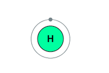
Hydrogen atom electron shell diagram
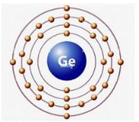
Germanium atom electron shell diagram

Arsenic atom electron shell diagram

Indium atom electron shell diagram
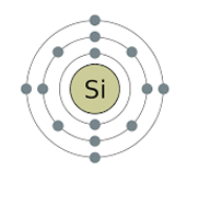
Silicon atom electron shell diagram
To have a flow of current in an electrical circuit, certain conditions must be met. Here is a breakdown of the essential requirements:
Electrons need a continuous, unbroken path to flow. This means the circuit must form a complete loop from the power source's negative terminal to its positive terminal. Any break in the circuit, such as an open switch or a broken wire, will stop the current flow.
A voltage source, like a battery or generator, provides the "push" that forces electrons to move. This "push" is known as potential difference, measured in volts. Without a voltage source, there's no force to drive the electrons through the circuit.
The circuit must include a conductive material, such as copper wire, that allows electrons to flow relatively freely. Conductors have many free electrons that can easily move when a voltage is applied.
Think of it like a water circuit: you need a pump (voltage source) to push the water (electrons) through a continuous pipe (closed circuit) made of a material that allows water to flow (conductor).
These three conditions are fundamental for establishing and maintaining an electrical current.
Definition: Energy per unit charge supplied by a source.
Unit: Volt (V)
Formula: EMF (ε) = Work (W) / Charge (Q)
Definition: Difference in electrical potential between two points.
Unit: Volt (V)
Formula: PD (V) = Work (W) / Charge (Q)
Definition: Rate of flow of electric charge.
Unit: Ampere (A)
Formula: Current (I) = Charge (Q) / Time (t)
Definition: Opposition to the flow of electric current.
Unit: Ohm (Ω)
Formula: Resistance (R) = Voltage (V) / Current (I) (Ohm's Law)
Definition: Rate at which electrical energy is transferred.
Unit: Watt (W)
Formulas:
Definition: Intrinsic property of a material opposing current flow.
Unit: Ohm-meter (Ω·m)
Formula: Resistivity (ρ) = (Resistance (R) × Area (A)) / Length (L)
Definition: How resistance changes with temperature.
Unit: Per degree Celsius (°C-1) or per Kelvin (K-1)
Formula: Rt = R0[1 + α(T – T0)]
Definition: Fundamental property of matter causing electromagnetic force.
Unit: Coulomb (C)
Formula: Charge (Q) = Current (I) × Time (t)
Electricity has a wide range of effects, which are the basis for its many applications: 1
When electric current flows through a conductor, it generates heat due to the resistance of the conductor. 2 This is known as Joule heating.
Examples: Electric heaters, toasters, incandescent light bulbs. 3
An electric current produces a magnetic field around the conductor. 4
Examples: Electromagnets, electric motors, generators. 5
Electric current can cause chemical reactions, such as electrolysis. 6
Examples: Electroplating, battery charging, production of chemicals. 7
Electricity can excite atoms, causing them to emit light.
Examples: LED lights, fluorescent lights, arc lamps.
Electric current can affect living organisms, including muscle stimulation and nerve impulses. 8
Examples: Medical devices (pacemakers, defibrillators), electric shocks.
Electricity is used in countless applications across various fields: 9
Providing electricity to homes, businesses, and industries. 10
Computers, smartphones, televisions, radio, and the internet.
Electric vehicles, trains, and aircraft.
Manufacturing, automation, and robotics.
Diagnostic equipment, treatment devices, and life support systems. 11
Household and industrial lighting, and heating of homes and businesses. 12
States that the voltage across a conductor is directly proportional to the current flowing through it, provided the temperature 13 remains constant. 14
Formula: V = IR (Voltage = Current × Resistance) 15
Application: Used to calculate voltage, current, or resistance in a circuit. 16
States that the total current entering a junction (node) in a circuit is equal to the total current leaving the junction.
Application: Used to analyze current distribution in complex circuits.
States that the algebraic sum of the voltages around any closed loop in a circuit is equal to zero.
Application: Used to analyze voltage distribution in complex circuits.
States that the heat generated in a conductor is directly proportional to the square of the current, the resistance, and the time.
Formula: H = I2RT (Heat = Current² × Resistance × Time) 17
Application: Used to calculate heat dissipation in electrical components.
The power dissipated or consumed in a circuit is the product of voltage and current.
Formulas: P=VI, P=I2R, P=V2/R.
Application: used to calculate power consumption in a circuit. 18
Wiring according to specifications ensures safety, reliability, and functionality in electrical systems. 1 It involves adhering to established standards and practices.
Cable gauges (e.g., AWG - American Wire Gauge) indicate the wire's diameter and current-carrying capacity. 2 A lower gauge number means a thicker wire and higher current capacity. 3
Interpretation: Selecting the correct gauge is crucial to prevent overheating and voltage drops. 4
Colour codes (e.g., in North America: black for hot, white for neutral, green for ground; in Europe: brown for live, blue for neutral, green/yellow for earth) identify the function of wires.
Interpretation: Colour codes ensure proper connections and prevent wiring errors. 5
Terminal designations (e.g., L, N, E, +, -) indicate where wires should be connected.
Interpretation: Following terminal designations is essential for correct circuit operation.
PCBs are boards with conductive tracks that connect electronic components. 6
Interpretation: Understanding PCB layouts is necessary for troubleshooting and repairing electronic devices. 7
Circuit protection devices (e.g., fuses, circuit breakers) protect circuits from overcurrents and short circuits. 8
Interpretation: These devices are rated for specific currents and voltages, and must be matched to the circuit they are protecting. 9
Terminals are connection points for wires. 10 They come in various types, such as screw terminals, crimp terminals, and push-in terminals.
Interpretation: Choosing the correct terminal type and ensuring a secure connection are crucial for reliable performance.
Switches control the flow of electricity in a circuit. 11 They can be toggle switches, push-button switches, rotary switches, etc.
Interpretation: Understanding switch ratings and configurations (e.g., SPST, SPDT) is essential for selecting the appropriate switch.
Harnesses are organized bundles of wires that connect different parts of an electrical system. 12
Harness design involves planning the physical path of wires, securing them with clips or ties, and using protective sleeving. 14
Layouts are critical in automotive, aerospace, and industrial applications.
Harness designs must also take into account the flexibility and strain relief of the wires. 15