An electrical circuit is a closed loop that allows electricity to flow. It consists of
components like power sources, conductors, and loads. To represent these
components in a clear and concise manner, we use standardized symbols.
Standard Automobile Electrical Symbols
Here are some of the most common electrical symbols used in circuit diagrams:
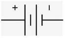
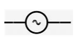
Power Source:
Battery: Represented by long and short parallel lines. The longer line
indicates the positive terminal.
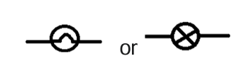
AC Source: Represented by a sine wave symbol.
Conductor:
Wire: Represented by a straight line.
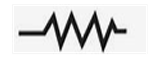
Resistor:
Fixed Resistor: Represented by a zigzag line.
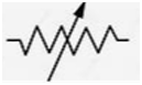
Variable Resistor (Potentiometer): Represented by a zigzag line with
an arrow in the middle.
Switch:
Single-Pole Single-Throw (SPST): Represented by two lines with a
gap that can be closed or opened.
Single-Pole Double-Throw (SPDT): Represented by two lines with a
gap that can connect to either of two other lines.
Lamp/Bulb:
Represented by a circle with a filament inside.
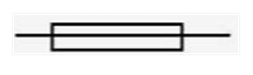
Fuse:
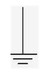
Ground:
Represented by a triangle or a ground symbol.
Drawing and Simple Circuits
Battery: Draw the battery symbol with the positive terminal on one side and
the negative terminal on the other.
Switch: Draw the switch symbol in series with the battery.
Lamp: Draw the lamp symbol in series with the switch.
Connect the Components: Connect the components using straight lines to
represent the wires.
Explanation:
When the switch is closed, the circuit is complete, and current flows from the
positive terminal of the battery, through the switch, the lamp, and back to the
negative terminal of the battery.
The lamp lights up because the current passing through its filament causes it
to heat up and emit light.
When the switch is open, the circuit is broken, and no current flows, so the
lamp remains off.
e.g
More Complex Circuits
You can build more complex circuits by adding components like resistors, capacitors,
inductors, and diodes. Each component has its own symbol, and their arrangement
in the circuit determines the overall behaviour of the circuit.
Series and Parallel Circuits
Series Circuit:
Components are connected one after another, forming a single path for
current to flow.
The current is the same through all components.
The voltage is divided among the components.
If one component fails, the entire circuit is broken.
Parallel Circuit:
Components are connected across the same two points, providing
multiple paths for current to flow.
The voltage is the same across all components.
The current is divided among the components.
If one component fails, the other components continue to operate.
Combination Circuit:
A circuit that contains both series and parallel connections.
Automobile Electrical Circuits
Here is how you identify these circuit types in an automobile:
Series Circuits:
Headlights (Older Systems): In older vehicles, headlights were
sometimes wired in series. If one bulb blew, both lights would go out.
This is less common in modern vehicles.
Some Sensor Circuits: Some simple sensor circuits may be wired in
series.
Indicators: very rarely, but it is possible to find indicator lights wired in
series.
Parallel Circuits:
Most Lighting Systems: Modern headlights, taillights, and interior
lights are typically wired in parallel. This ensures that if one bulb fails,
the others continue to operate.
Accessory Circuits: Power windows, power locks, and other
accessories are usually wired in parallel.
Fuse Boxes: Multiple circuits are connected in parallel to the battery
through the fuse box.
Horns: Most often wired in parallel.
Combination Circuits:
Complex Lighting Systems: Some lighting systems may have a
combination of series and parallel connections, especially in vehicles
with advanced lighting features.
Engine Control Systems: Engine control systems often involve
complex circuits with both series and parallel connections, including
sensors, actuators, and control modules.
Dashboard circuits: The dashboard often contains a mixture of series
and parallel circuits, to control various systems.
How to Identify in a Diagram:
Series: Look for a single path for current flow. If components are connected
one after the other, it's a series circuit.
Parallel: Look for multiple paths for current flow. If components are connected
across the same two points, it's a parallel circuit.
Combination: Look for a mix of series and parallel connections.
Practical Examples:
Imagine a string of old-style Christmas lights. If one bulb goes out, the whole
string goes dark—that's a series circuit.
Now, picture the lights in your car's interior. If one dome light bulb blows, the
others still work—that's a parallel circuit.
A modern vehicle's engine control unit will have a very complex circuit board,
that will contain many series and parallel circuits.
Measuring Current Density
Definition:
Current density is the amount of current flowing per unit cross
sectional area of a conductor. It's measured in amperes per square meter
(A/m²) or amperes per square millimeter (A/mm²).
Procedure:
Measure the Current: Use an ammeter to measure the current (I)
flowing through the conductor.
Measure the Cross-Sectional Area:
If the conductor is circular, measure its diameter (d) and
calculate the area (A) using the formula: A = π(d/2)².
If the conductor has a different shape, measure its dimensions
and calculate the area accordingly.
Calculate Current Density: Divide the current (I) by the cross
sectional area (A): Current Density (J) = I/A.
Practical Considerations:
Ensure the ammeter is connected in series with the conductor.
Use accurate measuring tools for the cross-sectional area.
Be aware of the conductor's temperature, as it can affect current
density.
Measuring Maximum Permissible Voltage Drop
Definition:
Voltage drop is the decrease in voltage along a conductor due to
its resistance. Maximum permissible voltage drop is the maximum allowable
voltage loss in a circuit.
Procedure:
Determine the Permissible Voltage Drop: This is usually specified in
standards or design requirements.
Measure the Voltage at the Source: Use a voltmeter to measure the
voltage (Vs) at the power source.
Measure the Voltage at the Load: Use a voltmeter to measure the
voltage (Vl) at the load.
Calculate the Voltage Drop: Subtract the load voltage (Vl) from the
source voltage (Vs): Voltage Drop (ΔV) = Vs - Vl.
Compare to Permissible Voltage Drop: Ensure the calculated
voltage drop is less than or equal to the maximum permissible voltage
drop.
Practical Considerations:
Measure the voltages under normal operating conditions.
Consider the length and gauge of the wire, as they affect voltage drop.
Account for temperature effects on conductor resistance.
Calculating Standard Wire Gauges
Definition:
Standard wire gauges (e.g., AWG) define the diameter and cross
sectional area of wires.
Calculation:
AWG is a logarithmic scale, and calculations can be complex.
In practical usage, it is best to use AWG charts, or online calculators.
If a calculation is needed, the formula is n = 36 - 19.931 * log(d), where
n is the AWG number and d is the diameter in inches.
For the most part, you will look up the wire gauge on a chart, and not
calculate it.
Practical Considerations:
Use AWG charts or online calculators for accurate conversions.
Select the appropriate gauge based on the current-carrying capacity
and voltage drop requirements.
Wire gauges have associated resistances per length, and current
carrying capacities.
Decoding Terminal Designations
Definition:
Terminal designations are alphanumeric codes that indicate the
function of a terminal on an electrical component.
Decoding:
Refer to the manufacturer's documentation or datasheets for the
specific component.
Common designations include:
L: Line (live)
N: Neutral
E or G: Earth (ground)
+: Positive
-: Negative
COM: Common
NO: Normally open
NC: Normally closed
Specific symbols for automotive relays, and other devices.
Automotive wiring diagrams may have unique codes for specific vehicle
systems.
Practical Considerations:
Always consult the relevant documentation.
Use a multimeter to verify terminal functions if necessary.
Pay attention to color codes, as they often correspond to terminal
functions.
Automotive Lighting Technologies
Conventional Bulb (Incandescent Bulb):
Construction: A thin tungsten filament is enclosed in a vacuum or
inert gas-filled glass bulb.
Operation: When an electric current passes through the filament, it
heats up and glows, emitting light. These bulbs are relatively
inexpensive but have a short lifespan and low efficiency, as much of
the energy is lost as heat.
Semi-Sealed Unit:
Construction: These units feature a replaceable bulb within a sealed
glass lens and reflector assembly.
Operation: They offer improved durability and weather resistance
compared to conventional bulbs. The replaceable bulb allows for
easier maintenance. However, they are less efficient than newer
technologies.
Quartz Halogen:
Construction: A tungsten filament is enclosed in a quartz glass bulb
filled with halogen gas.
Operation: The halogen gas reacts with evaporated tungsten,
redepositing it onto the filament, extending its lifespan and producing a
brighter, whiter light. They operate at higher temperatures than
conventional bulbs.
LED Lights (Light-Emitting Diodes):
Construction: Semiconductor devices that emit light when an electric
current passes through them.
Operation: LEDs are highly efficient, have a long lifespan, and
produce a bright, focused light. They are increasingly used in
automotive lighting for headlights, taillights, and interior lighting due to
their low power consumption and design flexibility.
Gas Ignited Lights (HID - High-Intensity Discharge):
Construction: These lights use an arc between two electrodes in a
gas-filled bulb to produce light.
Operation: HID lights, including xenon lights, produce a very bright,
white light. They are more efficient than halogen bulbs and have a
longer lifespan. They require a ballast to regulate the voltage and
current.
Xenon Lighting:
Construction: A type of HID lighting that uses xenon gas in the bulb.
Operation: Xenon lights produce a brilliant, bluish-white light. They
provide excellent visibility and are commonly used in high-end vehicles.
They require a ballast to start and maintain the arc.
Ultra Violet Headlights:
Construction: These lights emit ultraviolet (UV) light, which is then
converted to visible light by a phosphor coating.
Operation: While not common in standard automotive headlights due
to safety and regulatory concerns, UV technology is used in some
specialized applications. The UV light itself is not visible, the phosphor
coating is what creates the visable light.
Infrared Lights:
Construction: These lights emit infrared (IR) radiation.
Operation: IR lights are used in night vision systems and driver
assistance technologies. They are not used for standard headlights,
as the light emitted is outside of the visible spectrum. They are used in
systems that use cameras to detect heat signatures.
Selection of Bulbs Based on Power Ratings
Understanding Power Ratings (Watts):
A bulb's power rating, measured in watts (W), indicates the amount of
electrical energy it consumes. Higher wattage bulbs produce more light
but also draw more current.
Manufacturer Specifications:
Always refer to the vehicle's owner's manual or the manufacturer's
specifications for the correct bulb type and wattage for each lighting
application (headlights, taillights, turn signals, etc.).
Using bulbs with incorrect wattage can lead to:
Overheating: Higher wattage bulbs can generate excessive
heat, potentially damaging wiring, connectors, or the light
assembly itself.
Reduced visibility: Lower wattage bulbs may not provide
sufficient illumination, compromising safety.
Electrical system overload: Exceeding the circuit's current
capacity can blow fuses or damage components.
Legal Requirements:
In many jurisdictions, there are regulations regarding the type and
wattage of bulbs that can be used on vehicles. Using non-compliant
bulbs can result in fines or vehicle inspection failures.
Application-Specific Selection:
Headlights: Require bulbs with specific beam patterns and wattages to
provide adequate illumination without blinding oncoming drivers.
Taillights and Brake Lights: Need bulbs with sufficient brightness to
ensure visibility to other drivers.
Turn Signals: Require bulbs that flash at the correct rate. Incorrect
wattage can affect the flasher unit's operation.
Interior Lights: Usually lower wattage bulbs.
Use of Bulbs with Various Power Ratings
Replacing Bulbs:
When replacing a bulb, always use a bulb with the same wattage as
the original.
If upgrading to a higher performance bulb (e.g., halogen or LED),
ensure it is compatible with the vehicle's electrical system and meets
legal requirements.
LED Conversions:
LED bulbs are becoming increasingly popular as replacements for
conventional bulbs.
When converting to LED, ensure the LED bulb is compatible with the
vehicle's electrical system and that it provides the correct light output
and beam pattern.
LEDs often use much less power than the original bulbs, and this can
cause issues with the vehicles systems. Some vehicles will require the
addition of resistors to the circuit to prevent the vehicle from thinking
the bulb is broken.
Testing and Troubleshooting:
If a bulb is not working, check the fuse and wiring before replacing the
bulb.
Use a multimeter to test the voltage at the bulb socket to ensure the
circuit is functioning correctly.
Modifications:
Be very careful when modifying any lighting circuits. Any modification
could cause damage to the vehicles electrical system.
Adding extra lights, or changing the power rating of existing lights, can
overload the vehicles electrical system.
Explanation: The brake light switch closes when the brake pedal is
pressed, completing the circuit and lighting the brake lights.
Adaptive Front Lighting System (AFS) / Intelligent Front Lighting
Principle of Operation:
AFS is a sophisticated lighting system that adjusts the headlight beam
pattern based on various driving conditions. Its primary goal is to
optimize visibility while minimizing glare for other drivers.
Sensors:
AFS relies on a network of sensors, including:
Vehicle speed sensors
Steering angle sensors
Yaw rate sensors
Light sensors (to detect ambient light)
Control Unit:
A central control unit processes the sensor data and
calculates the optimal headlight beam pattern.
Actuators:
Actuators, such as small electric motors, adjust the position
and direction of the headlight beams.
Functions:
Curve Lighting: When the vehicle enters a curve, the
headlights swivel in the direction of the turn, illuminating the
road ahead.
Speed-Dependent Lighting: At higher speeds, the headlights
may project a longer and narrower beam to improve visibility at
a distance. At lower speeds, a wider beam may be used to
illuminate the immediate surroundings.
Weather-Dependent Lighting: Some AFS systems can adjust
the beam pattern based on weather conditions, such as rain or
fog.
Automatic Levelling: AFS systems often include automatic
levelling, which keeps the headlights aimed correctly regardless
of the vehicle's load or road conditions.
Glare Reduction: Modern systems use cameras to detect
oncoming traffic, and will adjust the high beams to not blind
other drivers, while still providing maximum illumination.
Benefits:
Improved visibility in various driving conditions.
Enhanced safety for the driver and other road users.