
Electrical and Electronics Fundamentals refers to the basic principles and concepts that govern the behaviour of electrical and electronic circuits and systems. It covers the foundational knowledge needed to understand how electrical and electronic devices operate, how they are constructed, and how they are applied.
• Definition:
o Passive components are electronic components that do not require an external power source to operate.
o They cannot amplify or generate electrical signals. Instead, they either dissipate, store, or release energy.
• Characteristics:
o They do not provide gain or amplification.
o They can control the flow of current and voltage.
o They can store or dissipate energy.
o Examples include resistors, capacitors, and inductors.
• Function:
o Resistors oppose the flow of electrical current.
o They convert electrical energy into heat, which is then dissipated, meaning it is released or dispersed into the surrounding environment, typically as thermal energy.
• Why they are passive:
o Resistors do not generate their own electrical signals.
o They do not amplify or increase the power of a signal.
o They simply resist the flow of current, causing a voltage drop and dissipating power as heat.
o They do not require an external power source to function.
Circuit symbols for the different types of resistors

• These resistors have a fixed resistance value determined by their material and construction. Carbon composition resistors use a mixture of carbon and a binder, while metal oxide resistors use a metal oxide film. They are commonly used for general-purpose applications.
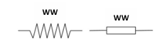
• These resistors are made by winding a resistive wire around a ceramic core. They are used for high-power applications and where precise resistance values are required.

• These resistors, also known as potentiometers, have a resistance value that can be adjusted mechanically. In a linear potentiometer, the resistance changes at a constant rate as you rotate the control knob.
For example, if you turn the knob halfway, the resistance will be approximately half of the total resistance
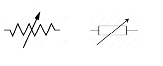
• These potentiometers also have an adjustable resistance, but the resistance change is logarithmic. The change in resistance is smaller at the beginning of the rotation and larger at the end.
This means that the resistance increases (or decreases) exponentially as you turn the knob
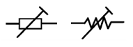
• These are small variable resistors designed for infrequent adjustments, often during circuit calibration. They are typically mounted on a circuit board and adjusted with a screwdriver.
• The nominal value is the intended or designated resistance of a resistor, measured in ohms (Ω).
• E12 Series: This is a standard series of preferred resistor values. It provides a logarithmic progression of values within each decade (e.g., 10-100 Ω, 100-1000 Ω). The E12 series has 12 values per decade, which are:
o 10, 12, 15, 18, 22, 27, 33, 39, 47, 56, 68, 82.
o To get other values you multiply those values by powers of 10. For example, 100, 120, 150, 180, 220, 270, 330, 390, 470, 560, 680, 820.
• Symbol: Ω (Ohm)
• The power rating indicates the maximum amount of power (in watts, W) that a resistor can safely dissipate as heat without being damaged. Exceeding the power rating can lead to overheating and failure.
• Factors: The power rating depends on the resistor's size, material, and construction.
• Symbol: W (Watt)
• Stability refers to how much the resistance value of a resistor changes over time or with variations in temperature, voltage, or humidity. High stability means the resistance remains relatively constant under different operating conditions.
• Factors:
o Temperature Coefficient: Measures the change in resistance per degree Celsius (°C).
o Voltage Coefficient: Measures the change in resistance per volt (V).
o Long-term Stability: Measures the change in resistance over the lifespan of the resistor.
• Units:
o Temperature Coefficient: ppm/°C (parts per million per degree Celsius)
o Voltage Coefficient: ppm/V (parts per million per Volt)
• Tolerance specifies the permissible deviation of the actual resistance value from the nominal value. It is expressed as a percentage (%). A lower tolerance indicates a more precise resistor.
• Example: A 100 Ω resistor with a 5% tolerance could have an actual resistance value between 95 Ω and 105 Ω.
• Symbol: % (Percentage)
• What it is: Colored bands on resistors tell you their resistance value and how accurate it is (tolerance).
• How it works: Each color stands for a number. You read the bands left to right.
| Color | Number | Multiplier | Tolerance |
|---|---|---|---|
| Black | 0 | 1 | - |
| Brown | 1 | 10 | ±1% |
| Red | 2 | 100 | ±2% |
| Orange | 3 | 1,000 | - |
| Yellow | 4 | 10,000 | - |
| Green | 5 | 100,000 | ±0.5% |
| Blue | 6 | 1,000,000 | ±0.25% |
| Violet | 7 | 10,000,000 | ±0.1% |
| Grey | 8 | 100,000,000 | - |
| White | 9 | 1,000,000,000 | - |
| Gold | - | 0.1 | ±5% |
| Silver | - | 0.01 | ±10% |
• Example (4 bands):
o Red, Red, Orange, Gold = 22,000 ohms (22 kΩ), ±5% tolerance.
• What it is: Numbers printed on resistors, especially small ones.
• How it works:
o "103" = 10 x 10³ (10,000) ohms = 10 kΩ.
o The first two numbers are the significant digits, the third number is the number of zeros.
o "R" means a decimal point. Example: 4R7 = 4.7 ohms.
Non-linear resistors are components where the resistance changes in a non-proportional way with variations in voltage, temperature, or light.1 This contrasts with linear resistors, which maintain a constant resistance.
o Thermistors are temperature-sensitive resistors.
o NTC (Negative Temperature Coefficient):
Their resistance decreases as temperature increases.
They are used for temperature sensing, temperature compensation, and inrush current limiting.
o PTC (Positive Temperature Coefficient):
Their resistance increases as temperature increases.
They are used for overcurrent protection, self-regulating heaters, and temperature sensing.
• Applications:
o Temperature measurement in thermostats, appliances, and industrial processes.
o Overheating protection in power supplies and electronic devices.
o Inrush current limiting in power supplies to prevent damage during start-up.
o Their resistance changes significantly with applied voltage.
o At low voltages, they have high resistance.
o At high voltages, their resistance drops sharply.
o They are used for surge protection.
• Applications:
o Protecting electronic circuits from voltage spikes and surges, such as those caused by lightning or power line fluctuations.12
o Used in power supplies, telecommunications equipment, and automotive electronics.
o Their resistance changes with the intensity of light.
o In darkness, they have high resistance.
o In bright light, their resistance decreases.
o They are used for light sensing and control.
• Applications:
o Automatic lighting control (streetlights, security lights).
o Light detection in cameras and light meters.
o Alarm systems and optical switches.
o This is a complete break in the resistor, causing infinite resistance.1
o Essentially, the resistor stops conducting electricity altogether.
• Causes:
o Overstress from excessive current or voltage.
o Physical damage (impact, bending).
o Thermal stress (overheating).
o Manufacturing defects.
• Effects:
o The circuit will not function as intended, as the current flow is interrupted.
o The resistor's value increases beyond its tolerance.
• Causes:
o Overheating.5
o Aging.
o Moisture ingress.
o Damage from voltage surges.
• Effects:
o The circuit's performance may degrade, or it may malfunction entirely. For example, a voltage divider may output the wrong voltage.
o The resistor's value decreases below its tolerance.
• Causes:
o Rare, but possible due to certain types of electrical overstress.
• Effects:
o Can lead to increased current flow, potentially damaging other components.
o In extreme cases, a resistor can effectively become a short circuit, meaning its resistance drops to near zero.6
• Causes:
o Severe electrical overstress.
o Physical damage.
• Effects:
o Can cause excessive current flow, leading to damage to other components, or even a fire hazard.7
• Overheating:
o Exceeding the resistor's power rating.
• Environmental Factors:
o Moisture, humidity, and temperature variations.
• Physical Stress:
o Impact, vibration, and mechanical stress.
• Electrical Stress:
o Voltage surges and excessive current.
• Manufacturing Defects:
o Errors during production.
• Aging:
o Components naturally degrade over time.
o Everything is made of atoms, which have positive (protons), negative (electrons), and neutral (neutrons) parts.1 Usually, things have the same number of positive and negative parts, so they are neutral. But, sometimes, electrons can move, making something have more or less negative charge.
o This imbalance of charges creates an electric charge. Objects can become charged by rubbing them together, which transfers electrons.2 Like charges repel each other (positive-positive or negative-negative), and opposite charges attract (positive-negative). The amount of charge is measured in Coulombs (C).
o This law tells us how strong the force is between two charged objects. The force is stronger when the charges are bigger and weaker when they are farther apart.
o Mathematically, it's expressed as: F = k * (q1 * q2) / r², where:
o This equation shows that the force is directly proportional to the product of the charges and inversely proportional to the square of the distance between them.11 12 Meaning if you double the charge of one object, the force doubles. If you double the distance between the objects, the force is reduced to one quarter of the original force.
o An electric field is the area around a charged object where another charged object will feel a force.14 Imagine it like an invisible force field.
o Electric field lines show the direction of the force.15 They go from positive to negative. The strength of the field is shown by how close the lines are together.16 A strong field means the lines are close.17
o The electric field (E) is defined as the force (F) per unit charge (q): E = F/q.18 The direction of the electric field is the direction of the force that a positive test charge would experience.
o This is the amount of energy needed to move a charged object in an electric field. It's like how high something is on a hill; it takes more energy to move it higher.
o Voltage is measured in volts (V). A higher voltage means there's more energy available to move charges.
o The voltage between two points is the difference in electric potential between them. It is defined as electrical potential energy per unit charge.
o This is the buildup of electric charge on the surface of an object. It often happens when two different materials are rubbed together, like when you rub a balloon on your hair.20
o The extra charge can then suddenly discharge, like when you get a shock from touching a doorknob.21 This is called an electrostatic discharge (ESD).
o When electrons move from one surface to another, one object will gain a net positive charge and the other object will have a net negative charge.
Capacitors store electrical energy in an electric field. They consist of two conductive plates separated by an insulating material called a dielectric.
• Paper Capacitors:

o Construction: Thin sheets of metal foil (the plates) are separated by waxed paper (the dielectric), then rolled into a cylindrical shape.
o Characteristics: Relatively inexpensive, moderate tolerance, and used in general-purpose applications. They are older technology, and less common now.
o Polarized/Non-Polarized: Typically non-polarized.
• Mica Capacitors:

o Construction: Thin sheets of mica (the dielectric) are sandwiched between metal foil plates.
o Characteristics: High stability, low losses, and high precision.4 Used in high-frequency applications.
o Polarized/Non-Polarized: Non-polarized.
• Ceramic Capacitors:
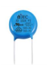
o Construction: A ceramic material (the dielectric) is coated with metal electrodes.6 Different types of ceramics provide varying properties.7
o Characteristics: Wide range of values, small size, and relatively inexpensive.8 Used in many general-purpose applications, and high frequency applications.9
o Polarized/Non-Polarized: Can be either, depending on the type of ceramic.
• Polyester Capacitors:
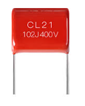
o Construction: Thin layers of polyester film (the dielectric) are sandwiched between metal foil plates, then rolled or stacked.10
o Characteristics: Good stability, high insulation resistance, and wide temperature range. Used in audio and general-purpose applications.
o Polarized/Non-Polarized: Non-polarized.
• Electrolytic Capacitors:
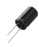
o Construction: One plate is a metal foil, and the other is an electrolyte. The dielectric is a thin oxide layer formed on the metal foil.
o Characteristics: High capacitance values in a small size. However, they are polarized, meaning they must be connected with the correct polarity.
o Polarized/Non-Polarized: Polarized.
o Types: Aluminum electrolytic, and tantalum electrolytic.

• Construction: Consists of two sets of metal plates, one fixed (stator) and one movable (rotor). Air is the dielectric.11 The capacitance is varied by rotating the rotor to change the overlap between the plates.12
• Characteristics: Used in radio tuning circuits, where precise capacitance adjustment is required.
• Polarized/Non-Polarized: Non-polarized.

• Construction: Small variable capacitors designed for infrequent adjustments.13 They often use ceramic or mica dielectrics.
• Characteristics: Used for fine-tuning circuits during calibration.
• Polarized/Non-Polarized: Typically non-polarized.
o The bigger the plates, the more charge the capacitor can hold. Think of it like a bigger bucket holding more water. More area equals more capacitance.
o The closer the plates, the stronger the electric field, and the more charge can be stored. Like magnets, the closer they are, the stronger the pull. Less distance means more capacitance.
o The stuff between the plates matters. Some materials allow for a stronger electric field than others. This is called the dielectric constant. A better material (higher constant) means more capacitance. It's like having a better insulator allowing more of an electrical charge to be held.
• Concept:
o When capacitors are connected in parallel, they effectively increase the total plate area.
o This leads to an increase in the overall capacitance.
• Calculation:
o To find the total capacitance (Ct) of capacitors in parallel, simply add the individual capacitances.
o Formula: Ct = C1 + C2 + C3 + ... + Cn
o Steps:
• Example:
o Imagine two buckets, one with a capacity of 10 litres and the other with 20 litres. If you pour both into a bigger container, the total volume is simply the sum of the two.
o Similarly, if you have capacitors C1 = 10 µF and C2 = 20 µF in parallel, the total capacitance is found by directly adding them: Ct = 10 µF + 20 µF = 30 µF.
o When capacitors are connected in series, they effectively increase the distance between the plates.
o This leads to a decrease in the overall capacitance.
• Calculation:
o To find the total capacitance (Ct) of capacitors in series, use the reciprocal formula.
o Formula: 1/Ct = 1/C1 + 1/C2 + 1/C3 + ... + 1/Cn
o Steps:
• Special Case (Two Capacitors):
o If you only have two capacitors in series, you can use a simplified formula: Ct = (C1 * C2) / (C1 + C2).
• Example:
o Step 1: Write down the formula.
o Step 2: Plug in the values.
o Step 3: Find a common denominator and add the fractions.
o Step 4: Invert the result to find Ct.
o Or using the special case formula.
Capacitor specifications define the characteristics and limitations of a capacitor.
• Explanation: This is the most fundamental specification, indicating the capacitor's ability to store charge.1 Measured in Farads (F), but often expressed in microfarads (µF), nanofarads (nF), or picofarads (pF).2
• Significance: Determines how much charge the capacitor can hold at a given voltage.
• Explanation: The maximum DC voltage that can be safely applied across the capacitor without risking dielectric breakdown.
• Significance: Exceeding this rating can lead to permanent damage or failure. It's crucial to select a capacitor with a voltage rating higher than the maximum voltage expected in the circuit.
• Explanation: The permissible deviation of the actual capacitance value from the nominal (specified) value, expressed as a percentage (%).
• Significance: Indicates the accuracy of the capacitor's capacitance. Lower tolerance values mean more precise capacitors.
• Explanation: The change in capacitance per degree Celsius (°C).
• Significance: Important for applications where temperature variations are significant. Some capacitors are more stable than others.
• Explanation: The internal resistance of a capacitor, which accounts for losses due to the leads, plates, and dielectric.
• Significance: Especially important in high-frequency applications, as ESR can affect performance and generate heat. Lower ESR is generally better.
• Explanation: The small DC current that flows through the capacitor's dielectric when a voltage is applied.
• Significance: Indicates the quality of the dielectric. Lower leakage current is desirable, especially in timing and filter circuits.
• Explanation: The insulating material between the capacitor plates (e.g., ceramic, electrolytic, film).7
• Significance: Determines the capacitor's characteristics, such as capacitance range, voltage rating, temperature stability, and frequency response.
• Explanation: The range of temperatures within which the capacitor can operate reliably.
• Significance: Ensures the capacitor can withstand the environmental conditions of the application.
• Explanation: How the capacitor's impedance and other characteristics change with frequency.
• Significance: Crucial for applications involving AC signals, such as filters and oscillators.
• Explanation: Indicates whether the capacitor has a defined positive and negative terminal.
• Significance: Polarized capacitors (e.g., electrolytic) must be connected with the correct polarity, while non-polarized capacitors can be connected either way.
o Just like resistors, capacitors also have preferred values, and the E12 series is one such standard.1
o The nominal value is the intended or specified capacitance of the capacitor, measured in Farads (F), but more often in microfarads (µF), nanofarads (nF), or picofarads (pF).
o The E12 series provides a set of 12 preferred values within each decade (e.g., 10 pF to 100 pF, 100 µF to 1000 µF).2
o These values are: 10, 12, 15, 18, 22, 27, 33, 39, 47, 56, 68, and 82.
o To get other values, those values are multiplied by powers of 10. For example 100pF, 120pF, 150pF, and so on.
• Significance:
o Using preferred values simplifies manufacturing, reduces costs, and ensures component availability.
o It helps in standardizing circuit designs.
o The working voltage, also known as the rated voltage, is the maximum DC voltage that a capacitor can safely handle continuously.
o It's important to understand that applying a voltage exceeding the working voltage can damage the capacitor's dielectric material, leading to breakdown and failure.
o The voltage is expressed in Volts (V).
• Significance:
o Selecting a capacitor with an appropriate working voltage is essential for circuit reliability.
o A general rule of thumb is to choose a capacitor with a working voltage that is significantly higher than the maximum voltage expected in the circuit to provide a safety margin.
o It is vital to check if the voltage is DC or AC, as AC voltages have peak values that must be considered.
• Explanation:
o Tolerance in capacitors indicates how much the actual capacitance value can vary from the nominal (stated) value.
o It's expressed as a percentage (%) or sometimes with letter codes.
o For example, a 100 µF capacitor with a ±10% tolerance could have an actual capacitance anywhere between 90 µF and 110 µF.
• Significance:
o Tolerance is important for applications where precise capacitance is critical, such as in timing circuits, filters, and oscillators.
o A lower tolerance value means the capacitor's actual value is closer to its nominal value, making it more accurate.
o General purpose capacitors often have a wider tolerance, while precision capacitors have a tighter tolerance.
o Therefore tolerance provides the designer with the range of values that the capacitor can be expected to have.
Dielectrics are insulating materials (meaning they don't conduct electricity easily) that can be polarized when an electric field is applied. This polarization is what makes them useful in capacitors and other electrical devices. Essentially, they store electrical energy by rearranging their internal charges.
o These materials have molecules where the positive and negative charges are normally evenly distributed. This means they don't have a natural dipole moment (no inherent separation of charges).
Think of these molecules like perfectly balanced balls.
When an electric field is applied, the charges within the molecules shift slightly, creating induced dipoles.
o Examples include:
Gases like air, nitrogen, and helium.
Non-polar liquids like benzene.
Materials like paraffin wax and polyethylene.
o These materials have molecules that already possess a permanent dipole moment, even without an external electric field. This means the positive and negative charges are naturally separated.
Think of these molecules like tiny magnets with a north and south pole.
The dipoles are randomly oriented, so the material as a whole has no net polarization.
When an electric field is applied, the dipoles tend to align themselves with the field, increasing polarization.
o Examples include:
Water.
Alcohol.
Some plastics.
o These are dielectrics where the polarization of the material is directly proportional to the applied electric field.
If you double the electric field, you double the polarization.
This makes them predictable and easier to work with.
o Many common dielectrics, both polar and non-polar, behave linearly within a certain range of electric field strengths.
o These are dielectrics where the polarization is not directly proportional to the applied electric field.
The relationship between polarization and electric field is more complex.
They may exhibit hysteresis (the polarization depends on the history of the applied field).
o Ferroelectric materials are an example of non-linear dielectrics. They can exhibit spontaneous polarization.
o These are a special type of polar dielectric that exhibit spontaneous polarization.
Even without an external electric field, they have a permanent polarization.
This polarization can be reversed by applying an electric field.
o They are used in applications like capacitors, sensors, and memory devices.
o Examples include:
Barium titanate.
Lead zirconate titanate (PZT).
• Similar to Resistors:
o The color code system is very similar to the resistor color code. Each color represents a numerical value.
• Units:
o Capacitance values determined from color codes are typically in picofarads (pF).
• Bands or Dots:
o Color codes can be presented as colored bands around the capacitor or as colored dots on its body.
• Key Components:
o Significant figures: The first few bands/dots indicate the significant digits of the capacitance.
o Multiplier: One band/dot acts as a multiplier, indicating the power of 10.
o Tolerance: Another band/dot may indicate the tolerance of the capacitor's value.
o Voltage Rating: sometimes a final band will indicate the voltage rating.
| Color | Digit | Multiplier | Tolerance |
|---|---|---|---|
| Black | 0 | 1 | ±20% |
| Brown | 1 | 10 | ±1% |
| Red | 2 | 100 | ±2% |
| Orange | 3 | 1,000 | - |
| Yellow | 4 | 10,000 | - |
| Green | 5 | 100,000 | ±5% |
| Blue | 6 | 1,000,000 | - |
| Violet | 7 | - | - |
| Grey | 8 | - | - |
| White | 9 | - | ±10% |
| Gold | - | 0.1 | ±5% |
| Silver | - | 0.01 | ±10% |
• Colors: Red, Yellow, Orange, Green
• Table
| Band 1 | Band 2 | Band 3 | Band 4 |
|---|---|---|---|
| Red | Yellow | Orange | Green |
| 2 | 4 | 1000 | ±5% |
• Calculation:
o (24) x 1,000 pF = 24,000 pF = 24 nF
o Tolerance: ±5%
• Description:
o This capacitor has a value of 24 nanofarads (nF), with a tolerance of plus or minus 5%.
• Colors: Brown, Black, Red, Silver
• Table:
| Band 1 | Band 2 | Band 3 | Band 4 |
|---|---|---|---|
| Brown | Black | Red | Silver |
| 1 | 0 | 100 | ±10% |
• Calculation:
o (10) x 100 pF = 1,000 pF = 1 nF
o Tolerance: ±10%
• Description:
o This capacitor has a value of 1 nanofarad (nF), with a tolerance of plus or minus 10%.
• Colors: Green, Blue, Brown.
• Table:
| Band 1 | Band 2 | Band 3 |
|---|---|---|
| Green | Blue | Brown |
| 5 | 6 | 10 |
• Calculation:
o (56) x 10 pF = 560 pF
• Description:
o This capacitor has a value of 560 picofarads (pF).
Inductance is essentially a circuit's opposition to changes in current. Here's a brief explanation:
• How it works:
• Key points:
o Description:
o Characteristics:
o Description:
o Characteristics:
o Description:
o Characteristics:
o Description:
o Characteristics:
o Definition:
o Impact:
o Example:
o Definition:
o Impact:
o Definition:
o Impact: