
When constructing and inspecting electronic circuits, it is essential to follow industry standards and safety guidelines to ensure reliability and functionality.
A basic electronic circuit consists of several key components:
• Identify the required components based on the circuit diagram.
• Check each component’s specifications and ratings.
• Follow standard schematic symbols and wiring layout.
• Ensure proper polarity (especially for diodes and electrolytic capacitors).
• Use a breadboard to test the circuit before soldering.6
• Check for short circuits or wrong connections.
• Once tested, transfer components to a PCB for a permanent setup.
• Use proper soldering techniques to ensure strong connections.
• Measure voltage, current, and resistance using a multimeter.
• Ensure circuit meets performance standards.
• ✔ IPC-A-600 – PCB acceptance standard.7
• ✔ IEC 61131 – Standard for industrial electronic circuits.8
• ✔ ISO 9001 – Ensures quality in electronics manufacturing.9
• ✔ IEEE Standards – Follow guidelines for circuit design and testing.
• ✔ Check for damaged components, loose connections, and soldering defects.10
• ✔ Verify component placement matches the circuit diagram.
• ✔ Measure voltage and current at key points using a multimeter.
• ✔ Ensure resistors, capacitors, and transistors are within specifications.
• ✔ Power ON the circuit and check for expected operation.
• ✔ Identify faulty components and replace if needed.
• ✔ Ensure proper insulation to prevent short circuits.
• ✔ Follow grounding and EMI (Electromagnetic Interference) standards.
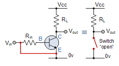
In this experiment, we will use a NPN transistor as a switch to control the flow of current through a load (like an LED) with a low control current at the base. When the transistor is ON, it allows current to flow from the collector to the emitter, turning the load on.13
• NPN Transistor (e.g., 2N2222)14
• Resistors:
o Base resistor (RB) = 1 kΩ (to limit base current)
o Load resistor (RL) = 220 Ω (for LED)
• Power Supply: 5V DC
• LED (Light Emitting Diode)15
• Switch (for base control)
• Connecting Wires
(not exactly aligning with explanation below)
• Power Supply (5V): Supplies the circuit with a constant voltage.
• Load Resistor RL: Limits the current flowing through the LED.
• LED: The load in the circuit, which will light up when the transistor is on.
• NPN Transistor: Acts as the switch.
o Base (B) is connected to the Switch with a current-limiting resistor.
o Collector (C) is connected to the LED and load resistor RL.
o Emitter (E) is connected to Ground (G).
• Switch: When closed, it allows current to flow to the base of the transistor and turn the transistor on.
• Base Resistor RB: Protects the base of the transistor by limiting the base current.
o When the switch is open, no current flows into the base of the transistor, and the transistor remains off.
o The LED remains off because no current flows through the collector and emitter.
o When the switch is closed, current flows into the base of the transistor through RB, which turns the transistor on.
o The transistor allows current to flow from the collector to the emitter, completing the circuit and allowing current to flow through the LED, which then lights up.
• The base current required to turn the transistor on is controlled by the base resistor RB.
• The LED will light up as long as the transistor is on (i.e., base current is flowing).
• The transistor is acting as a switch, turning the LED on and off based on the control signal (from the switch). This simple experiment demonstrates how a transistor can be used as a switch to control the flow of current in a circuit, with a small control current at the base turning on or off a larger current at the collector. This is commonly used in applications like digital switching, amplification, and relay control.
A Darlington transistor is a pair of transistors connected together to form a single device with high current gain. This configuration is often used in switching applications due to its ability to amplify weak signals into stronger ones. The Darlington transistor arrangement can be used as a switching amplifier, where a small input signal can control a larger load, like an LED or a motor.
• Darlington Transistor (e.g., TIP120) – This is a pre-packaged Darlington transistor.
• Resistors:
o Base resistor RB (typically 1kΩ) to limit base current.
o Load resistor RL (typically 220Ω or as required by the load).
• Power Supply (e.g., 9V battery or DC power supply).
• Switch (to control the base current).
• LED or Motor (to act as the load).
• Connecting Wires.
.png)
typical example picture (not following explanation)
• Power Supply (9V): Provides the voltage for the circuit.
• Load Resistor RLR_L: Limits the current flowing through the LED or motor.1
• LED or Motor: Acts as the load. It will light up (LED) or turn (motor) when the transistor is on.
• Darlington Transistor (TIP120):
o The base of the Darlington transistor receives a small current that switches the collector-emitter path on.2
o Base (B) is controlled by the switch and base resistor RBR_B.
o Collector (C) is connected to the load.
o Emitter (E) is connected to Ground.
• Base Resistor RBR_B: This resistor controls the current flowing into the base of the Darlington transistor to turn it on.
• Switch: When the switch is closed, it sends a small current to the base of the Darlington transistor, causing it to turn on.
• When the switch is open, no current flows to the base of the Darlington transistor.
• The transistor is in the OFF state, and therefore, no current flows from the collector to the emitter.
• The LED remains off, or the motor doesn't rotate.
• When the switch is closed, a small current flows into the base of the Darlington transistor.
• The Darlington transistor has a high current gain, meaning that a small base current will cause a large collector current to flow.3
• This current flows through the LED or motor, turning the LED on or motor rotating.
• High Current Gain: A Darlington transistor has a very high current gain (often in the range of 1000 or more), so it requires very little base current to drive a much larger current through the collector-emitter path.4
• Voltage Drop: The Darlington pair has a higher voltage drop across the collector-emitter than a single transistor (usually around 1.2V), which is important to consider when choosing the power supply.
• Switching Speed: While Darlington transistors have high gain, they are slower to switch compared to regular transistors due to their increased number of junctions.5
• Amplification of weak signals into high current output for loads such as LEDs, motors, or relays.6
• Power switching in applications like PWM motor control, power amplification, and relay switching.7
• High Current Gain: Low base current results in large collector-emitter current, making them ideal for driving large loads.8
• Simplified Control: Since only a small current is required at the base, it's easy to control high-power circuits with low-power signals (e.g., microcontroller or logic circuit).
• Stable Operation: Offers stable operation with less likelihood of saturation or failure compared to using single transistors.
• Switching circuits are designed to turn on and off the flow of electrical current in a circuit.11 These circuits play a critical role in many applications, such as digital electronics, logic gates, amplifiers, and signal processing. In a switching circuit, the state of the switch (ON or OFF) determines whether the circuit is active or inactive.
• There are several types of switching circuits depending on the technology used.12 Some common switching circuits include:
o Mechanical Switches
o Solid-State Switches (Transistors, Thyristors, FETs)
o Relay-Based Switching Circuits
• Mechanical switches are physical devices that open or close a circuit.13 They are the simplest form of switching circuits.
• Operation: A physical action, like pressing a button, opens or closes the circuit.
• Example: A light switch that turns the lights on or off by physically opening or closing the circuit.
• Solid-state switches, unlike mechanical switches, use semiconductors to control current flow without moving parts.14 The most common solid-state switches are transistors.
• Transistor switches are the most widely used solid-state switches in digital electronics. Bipolar Junction Transistors (BJTs) and Field-Effect Transistors (FETs) are commonly used.
o NPN Transistor as a Switch: In a basic NPN transistor switching circuit, when a small current is applied to the base, it allows a larger current to flow from the collector to the emitter.
▪ ON state: When there is sufficient base current, the transistor turns on, allowing current to flow through the load.
▪ OFF state: When there is no base current, the transistor remains off, and no current flows.
• Example: +5V (DC) | [Load] | [Collector] [ NPN Transistor ] [Base] | [Switch] (ON/OFF) | [Ground]. When the switch is closed, current flows through the base, and the transistor turns on, allowing current to pass through the load (such as an LED).
• MOSFETs (Metal-Oxide-Semiconductor Field-Effect Transistors) can also act as a switch, especially in high-power applications.15
• They are controlled by the voltage applied to the gate rather than the current.
• A relay is an electrically operated switch.16 When current flows through the coil of a relay, it creates a magnetic field that closes or opens the contacts of the switch. Relays can switch high currents using a small control current.17
o Operation: Relays have two parts: a coil (electromagnet) and a set of contacts.18 When current flows through the coil, it activates the magnet, which moves the contacts.
o Example: A relay can be used in an automotive circuit to control high-power components like a starter motor or in a home automation system to control appliances. Relay Schematic: +5V (DC) ----[Relay Coil]---- [Ground] | (Magnetic contacts) | [Load] | [Ground].
• Transistor-based switching circuits are commonly used for amplification and control in digital logic and signal processing circuits.
o On/Off Operation: The transistor is either fully on (saturated) or completely off (cut-off).
o Example: A simple NPN transistor switch.
• Relays are used when high-voltage circuits need to be controlled by low-voltage circuits (such as microcontrollers).19
o Control High Power Loads: A microcontroller can control a relay to turn on/off appliances.20
o Example: A home automation system where a relay switches an appliance on/off.
Loading question...
When constructing and inspecting electronic circuits, it is essential to follow industry standards and safety guidelines to ensure reliability and functionality.
A basic electronic circuit consists of several key components:
• Identify the required components based on the circuit diagram.
• Check each component’s specifications and ratings.
• Follow standard schematic symbols and wiring layout.
• Ensure proper polarity (especially for diodes and electrolytic capacitors).
• Use a breadboard to test the circuit before soldering.6
• Check for short circuits or wrong connections.
• Once tested, transfer components to a PCB for a permanent setup.
• Use proper soldering techniques to ensure strong connections.
• Measure voltage, current, and resistance using a multimeter.
• Ensure circuit meets performance standards.
• ✔ IPC-A-600 – PCB acceptance standard.7
• ✔ IEC 61131 – Standard for industrial electronic circuits.8
• ✔ ISO 9001 – Ensures quality in electronics manufacturing.9
• ✔ IEEE Standards – Follow guidelines for circuit design and testing.
• ✔ Check for damaged components, loose connections, and soldering defects.10
• ✔ Verify component placement matches the circuit diagram.
• ✔ Measure voltage and current at key points using a multimeter.
• ✔ Ensure resistors, capacitors, and transistors are within specifications.
• ✔ Power ON the circuit and check for expected operation.
• ✔ Identify faulty components and replace if needed.
• ✔ Ensure proper insulation to prevent short circuits.
• ✔ Follow grounding and EMI (Electromagnetic Interference) standards.
In this experiment, we will use a NPN transistor as a switch to control the flow of current through a load (like an LED) with a low control current at the base. When the transistor is ON, it allows current to flow from the collector to the emitter, turning the load on.13
• NPN Transistor (e.g., 2N2222)14
• Resistors:
o Base resistor (RB) = 1 kΩ (to limit base current)
o Load resistor (RL) = 220 Ω (for LED)
• Power Supply: 5V DC
• LED (Light Emitting Diode)15
• Switch (for base control)
• Connecting Wires
(not aligning with explanation below)
• Power Supply (5V): Supplies the circuit with a constant voltage.
• Load Resistor RL: Limits the current flowing through the LED.
• LED: The load in the circuit, which will light up when the transistor is on.
• NPN Transistor: Acts as the switch.
o Base (B) is connected to the Switch with a current-limiting resistor.
o Collector (C) is connected to the LED and load resistor RL.
o Emitter (E) is connected to Ground (G).
• Switch: When closed, it allows current to flow to the base of the transistor and turn the transistor on.
• Base Resistor RB: Protects the base of the transistor by limiting the base current.
o When the switch is open, no current flows into the base of the transistor, and the transistor remains off.
o The LED remains off because no current flows through the collector and emitter.
o When the switch is closed, current flows into the base of the transistor through RB, which turns the transistor on.
o The transistor allows current to flow from the collector to the emitter, completing the circuit and allowing current to flow through the LED, which then lights up.
• The base current required to turn the transistor on is controlled by the base resistor RB.
• The LED will light up as long as the transistor is on (i.e., base current is flowing).
• The transistor is acting as a switch, turning the LED on and off based on the control signal (from the switch). This simple experiment demonstrates how a transistor can be used as a switch to control the flow of current in a circuit, with a small control current at the base turning on or off a larger current at the collector. This is commonly used in applications like digital switching, amplification, and relay control.
A Darlington transistor is a pair of transistors connected together to form a single device with high current gain. This configuration is often used in switching applications due to its ability to amplify weak signals into stronger ones. The Darlington transistor arrangement can be used as a switching amplifier, where a small input signal can control a larger load, like an LED or a motor.
• Darlington Transistor (e.g., TIP120) – This is a pre-packaged Darlington transistor.
• Resistors:
o Base resistor RB (typically 1kΩ) to limit base current.
o Load resistor RL (typically 220Ω or as required by the load).
• Power Supply (e.g., 9V battery or DC power supply).
• Switch (to control the base current).
• LED or Motor (to act as the load).
• Connecting Wires.
typical example picture (not following explanation)
• Power Supply (9V): Provides the voltage for the circuit.
• Load Resistor RLR_L: Limits the current flowing through the LED or motor.1
• LED or Motor: Acts as the load. It will light up (LED) or turn (motor) when the transistor is on.
• Darlington Transistor (TIP120):
o The base of the Darlington transistor receives a small current that switches the collector-emitter path on.2
o Base (B) is controlled by the switch and base resistor RBR_B.
o Collector (C) is connected to the load.
o Emitter (E) is connected to Ground.
• Base Resistor RBR_B: This resistor controls the current flowing into the base of the Darlington transistor to turn it on.
• Switch: When the switch is closed, it sends a small current to the base of the Darlington transistor, causing it to turn on.
• When the switch is open, no current flows to the base of the Darlington transistor.
• The transistor is in the OFF state, and therefore, no current flows from the collector to the emitter.
• The LED remains off, or the motor doesn't rotate.
• When the switch is closed, a small current flows into the base of the Darlington transistor.
• The Darlington transistor has a high current gain, meaning that a small base current will cause a large collector current to flow.3
• This current flows through the LED or motor, turning the LED on or motor rotating.
• High Current Gain: A Darlington transistor has a very high current gain (often in the range of 1000 or more), so it requires very little base current to drive a much larger current through the collector-emitter path.4
• Voltage Drop: The Darlington pair has a higher voltage drop across the collector-emitter than a single transistor (usually around 1.2V), which is important to consider when choosing the power supply.
• Switching Speed: While Darlington transistors have high gain, they are slower to switch compared to regular transistors due to their increased number of junctions.5
• Amplification of weak signals into high current output for loads such as LEDs, motors, or relays.6
• Power switching in applications like PWM motor control, power amplification, and relay switching.7
• High Current Gain: Low base current results in large collector-emitter current, making them ideal for driving large loads.8
• Simplified Control: Since only a small current is required at the base, it's easy to control high-power circuits with low-power signals (e.g., microcontroller or logic circuit).
• Stable Operation: Offers stable operation with less likelihood of saturation or failure compared to using single transistors.
• Switching circuits are designed to turn on and off the flow of electrical current in a circuit.11 These circuits play a critical role in many applications, such as digital electronics, logic gates, amplifiers, and signal processing. In a switching circuit, the state of the switch (ON or OFF) determines whether the circuit is active or inactive.
• There are several types of switching circuits depending on the technology used.12 Some common switching circuits include:
o Mechanical Switches
o Solid-State Switches (Transistors, Thyristors, FETs)
o Relay-Based Switching Circuits
• Mechanical switches are physical devices that open or close a circuit.13 They are the simplest form of switching circuits.
• Operation: A physical action, like pressing a button, opens or closes the circuit.
• Example: A light switch that turns the lights on or off by physically opening or closing the circuit.
• Solid-state switches, unlike mechanical switches, use semiconductors to control current flow without moving parts.14 The most common solid-state switches are transistors.
• Transistor switches are the most widely used solid-state switches in digital electronics. Bipolar Junction Transistors (BJTs) and Field-Effect Transistors (FETs) are commonly used.
o NPN Transistor as a Switch: In a basic NPN transistor switching circuit, when a small current is applied to the base, it allows a larger current to flow from the collector to the emitter.
▪ ON state: When there is sufficient base current, the transistor turns on, allowing current to flow through the load.
▪ OFF state: When there is no base current, the transistor remains off, and no current flows.
• Example: +5V (DC) | [Load] | [Collector] [ NPN Transistor ] [Base] | [Switch] (ON/OFF) | [Ground]. When the switch is closed, current flows through the base, and the transistor turns on, allowing current to pass through the load (such as an LED).
• MOSFETs (Metal-Oxide-Semiconductor Field-Effect Transistors) can also act as a switch, especially in high-power applications.15
• They are controlled by the voltage applied to the gate rather than the current.
• A relay is an electrically operated switch.16 When current flows through the coil of a relay, it creates a magnetic field that closes or opens the contacts of the switch. Relays can switch high currents using a small control current.17
o Operation: Relays have two parts: a coil (electromagnet) and a set of contacts.18 When current flows through the coil, it activates the magnet, which moves the contacts.
o Example: A relay can be used in an automotive circuit to control high-power components like a starter motor or in a home automation system to control appliances. Relay Schematic: +5V (DC) ----[Relay Coil]---- [Ground] | (Magnetic contacts) | [Load] | [Ground].
• Transistor-based switching circuits are commonly used for amplification and control in digital logic and signal processing circuits.
o On/Off Operation: The transistor is either fully on (saturated) or completely off (cut-off).
o Example: A simple NPN transistor switch.
• Relays are used when high-voltage circuits need to be controlled by low-voltage circuits (such as microcontrollers).19
o Control High Power Loads: A microcontroller can control a relay to turn on/off appliances.20
o Example: A home automation system where a relay switches an appliance on/off.
• 1. ON State (Closed): In this state, the switch is closed, allowing current to flow through the load. For transistors, this means the transistor is conducting, allowing the current to pass from the collector to the emitter.
• 2. OFF State (Open): In this state, the switch is open, and no current flows through the load. For transistors, the transistor is in cutoff mode, and no current passes from the collector to the emitter.21
• Digital Logic Circuits: Used in AND, OR, NOT, NAND, NOR gates, where switches represent binary logic states (0 or 1).22
• Amplifiers: Switching circuits in amplifiers control signal flow through the circuit.
• Motor Control: Transistors and relays are used to control the speed and direction of motors in industrial machines or robotic arms.
• Home Automation: Relays are used to switch appliances, lights, and other electrical devices based on a control signal.23
• Pulse Width Modulation (PWM): Used in motor drivers and dimming circuits, where the switching circuit turns the load on/off rapidly to control power.24
• Resistors – Limit current and prevent overloading.25
• Capacitors – Filter signals or smooth out voltage spikes.26
• Inductors – Store energy and reduce high-frequency noise.27
• Transistors – Amplify or switch signals.28
• Relays – Switch high-power circuits.29
• Diodes – Control direction of current, used for flyback protection in relay circuits.30
• Switches – Basic control input to turn the circuit on or off.
• Oscillators are circuits that generate continuous periodic waveforms without requiring an external signal.31 These circuits are essential in a wide variety of electronic devices for generating clock signals, radio frequencies, sound, etc. They use feedback to sustain oscillations.
• An oscillator consists of two main components: an amplifier and a feedback network. The amplifier amplifies the signal, and the feedback network feeds part of the output back to the input.32
• The feedback must be in phase.
• Clock Generation in computers and digital circuits.
• Signal Generation in RF (Radio Frequency) circuits.
• Tone Generation in audio circuits.
• Frequency Synthesis in communication systems.
• The astable multivibrator is a type of flip-flop circuit that continuously switches between its two unstable states, generating a square wave signal.
• It has no stable state; hence, it oscillates indefinitely between two states.
• Typically built using transistors or op-amps with resistors and capacitors to set the timing of the oscillations.
• The general operation involves charging and discharging a capacitor to control the switching between the two states. The output is a square wave signal with a specific frequency.
• Pulse generation: Used in digital circuits, timers, and clock pulses.
• Tone generation: In audio applications like sound generators or alarms.
• PWM (Pulse Width Modulation): Used in controlling motor speed or dimming LEDs.
• The monostable multivibrator has one stable state and one unstable state. When triggered by an external pulse, the circuit switches to the unstable state for a fixed time period, after which it automatically returns to the stable state.
• The time spent in the unstable state is controlled by resistor and capacitor values in the circuit.
• Pulse stretching: Used for time delays, pulse width modulation.
• Timers: In circuits where a single pulse is required for a specific duration (e.g., in timers or triggering systems).
• Debouncing: Used in switches to eliminate false triggers.
• The bistable multivibrator, also known as a flip-flop, has two stable states. It remains in one of these states until triggered by an input signal to switch to the other stable state.
• Once triggered, it remains in its new state without any further input, making it ideal for storing binary data (0 or 1).
• The bistable multivibrator uses feedback to maintain one of the two states. The output can only change when triggered by an appropriate input signal.
• Data storage: Used in registers, memory cells, and flip-flops in digital circuits.
• Binary counters: Forms the building block of counters used in clocks and timers.
• State machines: Used in systems that need to maintain and change states based on inputs (e.g., digital systems, CPUs).
• The Schmitt trigger is a type of comparator that introduces hysteresis to the switching threshold. It has two distinct threshold voltages: one for transitioning from low to high and another for transitioning from high to low.
• This hysteresis prevents noise from causing erratic switching in digital circuits, ensuring a cleaner transition between logic levels.
• It is a digital circuit used to convert noisy or analog signals into clean, sharp square waves.
• The Schmitt trigger uses positive feedback to create the hysteresis effect. Once the input voltage exceeds one threshold, it flips to the opposite output state and remains there until the input crosses the other threshold.
• Noise reduction: Used in noisy environments to clean up signals.
• Signal conditioning: Used in analog-to-digital conversion to convert slow or noisy signals into a clean digital output.
• Oscillator circuits: Can be used as part of a waveform generator.
• Pulse Shaping: In communication circuits, for sharp edges in pulses.
| Oscillator Type | Stable States | Output | Applications |
|---|---|---|---|
| Astable Multivibrator | No stable state (free-running) | Continuous square wave | Pulse generation, PWM, tone generation, clock generation. |
| Monostable Multivibrator | One stable state | Single pulse output | Timers, pulse width modulation, signal filtering. |
| Bistable Multivibrator | Two stable states | Binary output (0 or 1) | Memory storage, binary counters, state machines, flip-flops. |
| Schmitt Trigger | Two threshold states | Clean digital signal | Noise filtering, signal conditioning, waveform shaping, pulse shaping. |
Digital circuits are a type of electronic circuit that uses discrete signals to represent data in the form of binary values (0s and 1s). Unlike analog circuits, which deal with continuous signals, digital circuits operate with two distinct voltage levels, typically corresponding to logic low (0) and logic high (1). Digital circuits are fundamental in modern electronics, powering devices such as computers, phones, and digital signal processing systems.
Digital circuits are based on Boolean algebra and logic gates, where binary signals (0 and 1) are processed to perform various logical operations. The basic components of digital circuits are:
Digital circuits can be broadly categorized into two main types:
• Combinational Circuits
• Sequential Circuits
Combinational circuits are circuits whose output depends only on the current input values. There is no memory involved; the output is determined by the combination of inputs.
• Logic Gates (𝐴𝑁𝐷,𝑂𝑅,𝑁𝑂𝑇,𝑁𝐴𝑁𝐷,𝑁𝑂𝑅,𝑋𝑂𝑅,𝑋𝑁𝑂𝑅)
• Adders (Half Adder, Full Adder)
• Multiplexers: Used to select one of several input signals and pass it to the output.
• Encoders/Decoders: Convert binary data to different formats or vice versa.
A half adder adds two binary digits (bits) and produces a sum and a carry as the output.
• Inputs: A, B (two bits to be added)
• Outputs: Sum (S), Carry (C)
The sum and carry are calculated as follows:
• Sum (S) = A 𝑋𝑂𝑅 B
• Carry (C) = A AND B
Sequential circuits are circuits whose output depends on both the current inputs and the past history of inputs. These circuits have memory elements like flip-flops that store previous states. Sequential circuits are used in systems where the output needs to change based on both the present input and the sequence of past inputs.
• Flip-Flops: Memory devices that store one bit of information (e.g., D flip-flop, JK flip-flop, T flip-flop).
• Registers: Used for storing multiple bits of data.
• Counters: Used to count the number of clock cycles or events in digital systems.
• State Machines: Systems that transition between different states based on inputs, often used in control systems.
• D Flip-Flop has a data input (D), a clock input (CLK), and an output (Q).
• The value at D is transferred to Q when a clock pulse (rising edge) is received. Otherwise, the value of Q remains unchanged.
Logic gates perform the basic operations of Boolean algebra, processing binary inputs to produce outputs. Each gate has its own truth table.
o AND Gate: Output is 1 only if both inputs are 1.
o OR Gate: Output is 1 if at least one input is 1.
o NOT Gate: Inverts the input (i.e., changes 1 to 0 and 0 to 1).
A multiplexer is a circuit that selects one of many input signals and forwards it to a single output based on select lines.
A demultiplexer is the reverse of a multiplexer. It takes one input signal and directs it to one of many outputs based on select lines.
Flip-flops are memory elements that store binary data. They have at least one input, a clock signal, and an output.
A counter is a sequential circuit used to count events or clock pulses. It can be up-counter, down-counter, or up/down-counter, depending on the counting direction.
A register is a group of flip-flops used to store multiple bits of information. Registers are used in computers and digital systems to store intermediate data.
Digital circuits are the foundation of computer architecture, handling operations such as arithmetic, logic, memory storage, and data transfer.
Digital circuits are used in audio processing, video processing, and communications for filtering, amplification, and modulation.
Digital circuits are used in state machines and controllers for automated systems, such as industrial machines and robotics.
Digital circuits are crucial in data transmission and error correction in wireless communication, satellite communication, and networking.
Embedded systems such as smartphones, home automation, and IoT devices rely heavily on digital circuits.
A Full Adder adds three binary digits: two data bits (A, B) and a carry-in bit (Cin). It produces two outputs: the Sum (S) and the Carry-out (Cout).
| A | B | Cin | Sum (S) | Carry-out (Cout) |
|---|---|---|---|---|
| 0 | 0 | 0 | 0 | 0 |
| 0 | 0 | 1 | 1 | 0 |
| 0 | 1 | 0 | 1 | 0 |
| 0 | 1 | 1 | 0 | 1 |
| 1 | 0 | 0 | 1 | 0 |
| 1 | 0 | 1 | 0 | 1 |
| 1 | 1 | 0 | 0 | 1 |
| 1 | 1 | 1 | 1 | 1 |
• Sum (S) = A XOR B XOR Cin
• Carry-out (Cout) = (A AND B) OR (Cin AND (A XOR B))
Logic gates are the fundamental building blocks of digital circuits. They perform logical operations on binary inputs and produce a single output based on the operation. Logic gates can be represented using both symbols and truth tables, which show the output for every combination of input values.
Symbol:
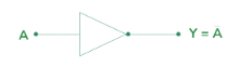
Switch Arrangement: A NOT gate inverts the input, meaning it outputs the opposite of the input.
| Input (A) | Output (Y) |
|---|---|
| 0 | 1 |
| 1 | 0 |
Boolean Expression: Y = A' (A prime, or NOT A)
Symbol:
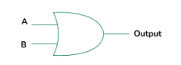
Switch Arrangement: An OR gate outputs 1 if at least one of the inputs is 1. Otherwise, it outputs 0.
| Input (A) | Input (B) | Output (Y) |
|---|---|---|
| 0 | 0 | 0 |
| 0 | 1 | 1 |
| 1 | 0 | 1 |
| 1 | 1 | 1 |
Boolean Expression: Y = A + B
Symbol:
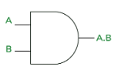
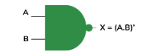
Switch Arrangement: An AND gate outputs 1 only if both inputs are 1. Otherwise, it outputs 0.
| Input (A) | Input (B) | Output (Y) |
|---|---|---|
| 0 | 0 | 0 |
| 0 | 1 | 0 |
| 1 | 0 | 0 |
| 1 | 1 | 1 |
Boolean Expression: Y = A * B
Switch Arrangement: A NAND gate is the opposite (inverter) of the AND gate. It outputs 0 only when both inputs are 1. Otherwise, it outputs 1.
| Input (A) | Input (B) | Output (Y) |
|---|---|---|
| 0 | 0 | 1 |
| 0 | 1 | 1 |
| 1 | 0 | 1 |
| 1 | 1 | 0 |
Boolean Expression: Y = (A * B)' (The NOT of A AND B)
Symbol:
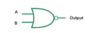
Switch Arrangement: A NOR gate is the opposite (inverter) of the OR gate. It outputs 1 only when both inputs are 0. Otherwise, it outputs 0.
| Input (A) | Input (B) | Output (Y) |
|---|---|---|
| 0 | 0 | 1 |
| 0 | 1 | 0 |
| 1 | 0 | 0 |
| 1 | 1 | 0 |
Boolean Expression: Y = (A + B)' (The NOT of A OR B)
Symbol:
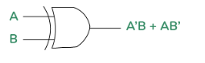
Switch Arrangement: An XOR gate outputs 1 if either input is 1, but not both. If both inputs are the same, it outputs 0.
| Input (A) | Input (B) | Output (Y) |
|---|---|---|
| 0 | 0 | 0 |
| 0 | 1 | 1 |
| 1 | 0 | 1 |
| 1 | 1 | 0 |
Boolean Expression: Y = A ⊕ B
Symbol:
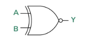
Switch Arrangement: An XNOR gate is the opposite (inverter) of the XOR gate. It outputs 1 if both inputs are the same (both 0 or both 1), and 0 if the inputs are different.
| Input (A) | Input (B) | Output (Y) |
|---|---|---|
| 0 | 0 | 1 |
| 0 | 1 | 0 |
| 1 | 0 | 0 |
| 1 | 1 | 1 |
Boolean Expression: Y = (A ⊕ B)'
Boolean algebra is used to simplify and represent logic combinations of variables. Here’s how we can use it to simplify expressions.
Expression: (A + B) × (A′ + C)
Expression: (A + B)′
• Apply De Morgan’s law: A′ × B′
Expression: (A × B) + (C′ × D)
• This represents an OR gate combining the outputs of an AND gate (A * B) and another AND gate (C' * D).
Expression: A ⋅ (B + C) + A′ ⋅ C
Final Simplified Expression: A ⋅ B + C
Expression: (A + B) ⋅ (C + D)′
Final Simplified Expression: A ⋅ C′ ⋅ D′ + B ⋅ C′ ⋅ D′
Expression: (A ⋅ B) + (C′ ⋅ D) + (A ⋅ C)
Final Simplified Expression: A ⋅ (B + C) + C′ ⋅ D
Pulse Code Modulation (PCM) is a method used to digitally represent analog signals, particularly for transmission or storage. PCM is widely used in audio systems (like CDs and DVDs) and telecommunication systems to convert analog signals into a digital form.
Input Analog Signal (Sound or Voice)
↓
Sampling (Analog signal is sampled at regular intervals)
↓
Quantization (Each sample is mapped to a discrete value)
↓
Encoding (Each quantized value is converted into a binary code)
↓
Transmission/Storage (The encoded binary signal is transmitted or stored)
A microprocessor is a central unit of a computer or any electronic system that performs processing tasks.
PCM is used in digital communication systems such as:
Microprocessors are used in:
Remote switching refers to the operation of controlling devices or circuits from a distance, typically through a communication network. 9 It is used in systems where the physical proximity to the equipment or device being controlled is not feasible, such as in power grids, telecommunications systems, or automation in industries.
Remote switches can be manual (where an operator switches the device remotely) or automated (controlled by pre-programmed logic based on inputs or schedules).
Multiplexing is a technique used in communication systems to combine multiple signals into a single data stream for transmission over a shared medium. 11 It allows more efficient use of available bandwidth by sending several signals simultaneously but using different time slots, frequency bands, or codes. 12
There are several types of multiplexing, including:
A decoder is a device used to convert a multiplexed signal back into its original individual components. 14 It decodes the combined signals based on the multiplexing scheme, allowing the receiver to separate the signals. 15
A data bus is a set of physical connections (such as wires or traces on a circuit board) that allow data to be transferred between different components within a system. 18 In the context of multiplexing, the data bus is used to transmit multiplexed signals between devices.
An address in multiplexing refers to the identifier used to select the specific signal or channel within a multiplexed stream. The address enables devices to correctly send or receive data from the appropriate source or destination.
Time Division is a multiplexing method in which the available transmission time is divided into small time slots. 22 Each signal or channel gets its turn to use the shared medium by sending data during its allocated time slot. 23
A mux (multiplexer) is a device used in multiplexing that combines multiple signals into a single signal for transmission over a shared medium. 25 The mux selects one of the input signals at a time based on a control signal and sends it to the output. 26
A demux (demultiplexer) is the reverse of a multiplexer. 29 It takes a single multiplexed input signal and separates it into its original individual signals based on a control signal.
| Component | Function | Example |
|---|---|---|
| Decoder | Converts a multiplexed signal into its individual components, reversing the multiplexing process. | Extracting voice channels from a TDM system. |
| Data Bus | A set of physical connections that carry multiplexed data between devices. | Data bus between CPU, memory, and peripherals. |
| Address | Identifies the specific channel or device in the multiplexed system, used for data routing. | Memory address in a computer system. |
| Time Division | Divides the transmission time into small time slots, each assigned to a signal or channel in time-division multiplexing. | TDM in digital telephony. |
| Mux (Multiplexer) | Combines multiple signals into one signal for transmission over a shared medium. | 2-to-1 multiplexer in digital communication. |
| Demux (Demultiplexer) | Separates a multiplexed signal into its original individual signals. | Demux in TV broadcasting to separate |
Loading question...
Sensors and actuators are essential components in modern vehicles. They provide feedback and control, allowing the vehicle to operate efficiently, safely, and according to the driver's commands. Sensors gather data from the vehicle's environment, while actuators use this data to take actions, such as adjusting engine settings or activating safety systems.
Below is a breakdown of some of the key sensors used in vehicles, explaining their construction and operation.
Sensors are devices that detect and measure physical quantities such as temperature, pressure, speed, or position. They convert these physical variables into electrical signals that can be read by a controller or a computer.
Construction and Operation:
Example: Fuel level sensors in vehicles measure the fuel inside the tank and send the data to the fuel gauge on the dashboard.
Construction and Operation:
Example: The throttle position sensor (TPS) measures the position of the throttle valve in an internal combustion engine.
Construction and Operation:
Example: The oxygen sensor (O2 sensor) in the exhaust system monitors the level of oxygen in the exhaust gases, allowing the engine management system to adjust the air-fuel mixture for optimal combustion.
Construction and Operation:
Example: If the knock sensor detects a knock in the engine, the ECU adjusts the timing of the spark to reduce knocking and improve performance.
Construction and Operation:
Example: The engine coolant temperature sensor measures the temperature of the coolant to ensure that the engine operates at the correct temperature.
Construction and Operation:
Example: The Mass Air Flow sensor (MAF) measures the mass of air entering the engine, which helps the ECU adjust the amount of fuel injected into the engine for optimal performance and fuel economy.
Actuators are devices that convert energy (usually electrical energy) into physical motion. 1 They are essential in control systems for performing tasks such as moving parts, controlling flow, or adjusting positions in vehicles and other machines. 2 Below is an explanation of different types of actuators, their construction, and operation.
A solenoid is a type of actuator that uses electromagnetic force to produce linear motion. 3 The basic construction of a solenoid consists of a coil of wire, typically wound around a cylindrical core. 4 When electric current flows through the coil, it creates a magnetic field that pulls or pushes a movable core (usually made of ferromagnetic material) inside the coil. 5
Construction:
Operation:
Example: Used in pinball machines, where the solenoid coil moves to push pins or triggers actions. 8
Construction:
Operation:
Example: Used
Construction:
Operation:
Example: Used in control valves, where the solenoid's motion can open or close the valve in both directions.
Construction:
Operation:
Example: Used in locking mechanisms in electronic door systems, where movement is required in both directions for unlocking and locking.
Electric motors are actuators that convert electrical energy into mechanical motion. 12 There are two primary types of electric motors used in actuator applications: linear motors and rotary motors. 13
Construction:
Operation:
Example: Used in elevators and automated assembly lines, where linear movement is necessary to lift or move parts along a straight path. 16
Construction:
Operation:
Example: Used in fans, pumps, electric vehicles, and conveyor belts, where rotational motion is needed to move parts or materials.
| Actuator Type | Description | Examples |
|---|---|---|
| Solenoid (Moving Winding) | A solenoid where the coil itself moves to create linear motion. | Pinball machines, electronic locks. |
| Solenoid (Moving Field) | The solenoid where the core moves within the coil to produce motion. | Valve actuators in industrial automation. |
| Double Acting Solenoid | A solenoid with two coils that allows bidirectional movement. | Control valves in hydraulic systems. |
| Double Wound Solenoid | A solenoid with two oppositely wound coils that offer more control over movement. | Electronic locking systems. |
| Linear Motor | A motor that provides straight-line motion instead of rotational motion. | Elevators, automated guided vehicles (AGVs). |
| Rotary Motor | A motor that converts electrical energy into rotational motion. | Fans, pumps, electric vehicles. |
When working with electronic circuits and vehicle systems, identifying and troubleshooting faults is a critical task. To carry out efficient fault diagnosis, we need to use specialized diagnostic equipment to detect, measure, and analyze the performance of systems. Here, we will focus on using Oscilloscopes, Engine Analysers, and Computerized Diagnostic Equipment to carry out fault diagnosis.
An oscilloscope is an essential diagnostic tool used to measure and visualize the time-varying signals (voltages) in a circuit. It's particularly useful for diagnosing faults in systems involving waveforms like sensors, signals, or power supplies.
Engine analysers are specialized diagnostic tools used to monitor, diagnose, and test various engine parameters. These devices are commonly used in automotive diagnostics to detect faults in the engine and its related systems, including the ignition, fuel, and emission systems.
Computerized diagnostic equipment, particularly OBD-II scanners, are essential in modern vehicles to detect faults in various systems. These scanners interface with the vehicle's computer system and provide information about performance, sensor data, and error codes.
| Equipment | Function | Fault Diagnostic Application |
|---|---|---|
| Oscilloscope | Measures time-varying signals, displays waveforms. | Detect irregular signals in sensors or circuits, measure voltages, and waveform quality. |
| Engine Analyzer | Reads error codes and analyzes engine parameters like fuel, ignition, and emission systems. | Detects issues in engine components (misfires, sensor failure, fuel system issues). |
| Computerized Diagnostic Equipment (OBD-II Scanner) | Communicates with vehicle’s ECU to read trouble codes, monitor real-time data, and clear error codes. | Retrieves and interprets fault codes from the vehicle’s ECU (sensor failures, emissions problems, etc.). |
On-Board Diagnostics (OBD-II) is a standardized system implemented in vehicles to monitor and evaluate the performance of the engine and other critical vehicle systems. By interfacing with the vehicle’s Engine Control Unit (ECU), OBD-II provides real-time data and fault codes that can help diagnose problems, optimize performance, and ensure compliance with emissions standards. Let's explore how to interpret digital signals, understand digital/graphical displays, and evaluate diagnostic data using OBD-II.
Digital signals from OBD-II systems are generally used to communicate real-time data from sensors, actuators, and the vehicle’s ECU. These digital signals are often transmitted as numerical values or coded messages that can represent various parameters such as engine speed, fuel pressure, oxygen sensor readings, and more.
Many modern OBD-II scanners and diagnostic tools feature digital and graphical displays to make interpreting diagnostic data easier. These displays can present sensor readings, error codes, and system performance data in a format that is more intuitive.
Diagnostic data from OBD-II provides crucial information to help evaluate the overall health of the vehicle’s systems. This data includes trouble codes, sensor readings, and system parameters that can help diagnose issues related to the engine, transmission, emissions, and more.
| OBD-II Feature | Description | Diagnostic Application |
|---|---|---|
| Digital Signals | Real-time sensor data in digital format (e.g., temperature, RPM, pressure). | Interprets sensor performance (e.g., coolant temp, RPM). |
| Digital Displays | Displays numeric values such as fuel pressure, throttle position, etc. | Real-time sensor data; check for out-of-range readings. |
| Graphical Displays | Visual representation of sensor data over time (e.g., oxygen sensor, fuel trims). | Spot trends, inconsistencies, and irregular sensor behavior. |
| Diagnostic Trouble Codes | Codes that indicate specific faults in the system (e.g., P0171, P0301). | Identify specific problems (misfire, emissions, etc.). |
| Live Data Evaluation | Continuous display of sensor readings (e.g., fuel trims, engine RPM). | Monitor system behavior and detect irregularities. |